


60
Toshiba
8-4.
Outdoor unit
control
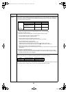
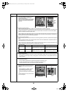
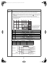
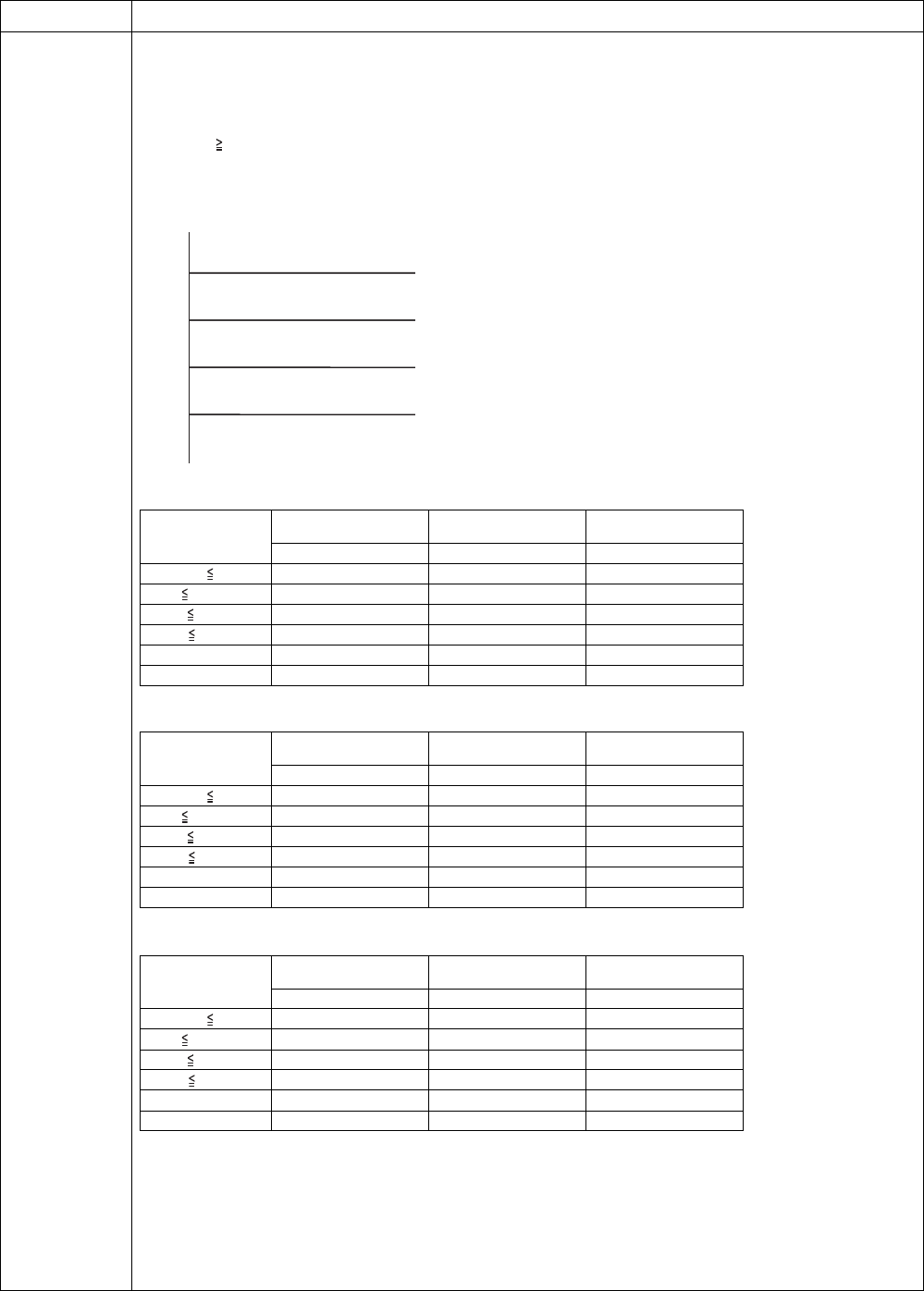
5-2)Hot water supply and heating fan control
1)The TE sensor, TO sensor and operation frequency control the outdoor fan.
(The minimum W1 to the maximum are controlled according to the table below.)
2)For 3 minutes after the start, the maximum fan tap for each zone that is shown in the following table is fixed. After
that, the fan is controlled according to the TE sensor temperature.
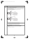
3) If TE 24°C continues for 5 minutes, the operation stops. No error code is displayed for this; the status is the same
as the usual thermostat off. The operation restarts after 150 seconds. This intermittent running is not abnormal.
4)If the situation in 3) frequently occurs, the possible cause is that the filter in the air inlet part of the hydro unit is
dusty. Clean the filter, and restart the operation.
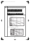
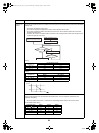
For 802H-E
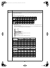
For 1102H-E
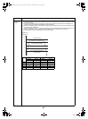
For 1402H-E
Item Operation flow and applicable data, etc.
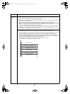
TE [
°C
]
24
21
18
15
-1 tap/20 secs (to W1)
-2 tap/20 secs (to W1)
-2 tap/20 secs (to W1)
Stop time count
Number of revolutions hold
+ 1 tap/20 secs
(Up to the maximum tap for each zone)
Temperature range
Less than 20 Hz
20 Hz or more to less
than 45 Hz
45 Hz or more
Maximum Maximum Maximum
10°C TO W7 W8 W9
5°C TO < 10°C W9 WB WD
-3°C TO < 5°C WD WD WE
-10°C TO < -3°C WE WE WE
TO < -10°C WF WF WF
TO abnormal WF WF WF
Temperature range
Less than 20 Hz
20 Hz or more to less
than 45 Hz
45 Hz or more
Maximum Maximum Maximum
10°C TO W7 W8 W9
5°C TO < 10°C W9 WA WA
-3°C TO < 5°C WA WA WB
-10°C TO < -3°C WB WB WB
TO < -10°C WD WD WD
TO abnormal WD WD WD
Temperature range
Less than 20 Hz
20 Hz or more to less
than 45 Hz
45 Hz or more
Maximum Maximum Maximum
10°C TO W7 W8 W9
5°C TO < 10°C W9 WA WB
-3°C TO < 5°C WB WB WC
-10°C TO < -3°C WC WC WC
TO < -10°C WD WD WD
TO abnormal WD WD WD
+00A09-002_01EN_SVM_ALL_Air_to_Water.book Page 60 Monday, October 5, 2009 2:09 PM