


21
Toshiba
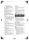
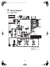
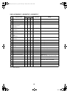
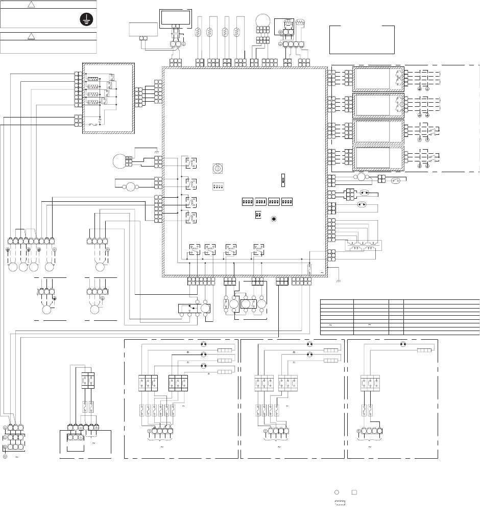
5 Wiring Diagram
5-1. Hydro Unit
11
33
1
2
3
4
5
6
1
4
5
6
2
3
WHI
WHI
Transformer
ORN
ORN
RED
RED
BRW
BRW
CN102
(WHI)
11
3
2
3
CN101
(WHI)
CN202
(YEL)
BLK
BLK
CN201
(WHI)
22
11
Thermal protector (auto)
75
± 3
High pressure switch
4.15MPa
RED
YEL
CN200
(RED)
2
33
1
7
2
GRN
22
8
1
CN211
(BLK)
2
3
4
1
Flow switch
4
1
CN210
(RED)
2
3
CN209
(GRN)
3
4
2
1
1
CN208
(BLU)
2
4
3
P.C.board
(MCC-1511)
1
3
2
CN213
(WHI)
1
3
1
2
1
CN214
(WHI)
2
6B6A
6C
6D
1
3
2
1
3
CN206
(WHI)
THO
2
1
CN205
(RED)
1
2
TWO
2
3
1
CN204
(BRW)
1
3
TWI
1
2
CN203
(YEL)
1
2
Remote
controller
(HWS-AMS11E)
CN41
(BLU)
1
1
2
3
3
7B7A
A
B
3
4
2
CN501
(YEL)
6
5
1
5
4
3
2
1
Relay
p.c.board
(MCC-1431)
55
11
4
3
2
2
3
4
3
1 1
2
3
2
1 1
3
55
4
6
9
7
8
7
9
CN01
(WHI)
CN02
(WHI)
11
33
SW01
WPM
CN601
(RED)
11
33
A1
A2
1
SW02
12
4
3
ON
4
3
21
ON
SW10
12
3
4
ON
SW11
3
21
4
SW12
ON
4
12
3
SW13
ON
21
SW06
ON
SW07
CN603
(YEL)
5 5
1
3
CN602
(WHI)
77
3
1
3
1
7
7
5
5
CN604
(BLU)
3
1
1
3
CN605
(YEL)
1
3
1
3
CN606
(BLU)
1
3
CN305
(GRN)
3
3
3
1
1
CN100
(WHI)
5
F100
Fuse
T5A
250V
Symbol
BLK
TC
RED
RED
BRW
BRW
RED
BLU
GRN
ORN
BRW
BLK
BLK
BLK
BLK
BLK
BLK
BLK
BLK
GRY
WHI
GRY
WHI
5251
53
54
59
55
WHI
RED
WHI
WHI
BLU
BRW
YEL
WHI
4241
44
43
WHI
YEL
WHI
RED
RED
WHI
GRY
A1
A2
6
4
8
7
A2
RY
02
A1
4
6
RY01
RY607RY606
8
7
5
6
4
2
RY
06
RED
WHI
BLK
YEL
RY
04
RY
01
YEL
BLU
BRW
RED
WHI
RED
ORN
WHI
PNK
WHI
ORN
WHI
PNK
WHI
1211
RED
13
GRY
RY
10
CR10
CR11
CR12
CR13
F01 (5A)
CN10
(WHI)
RY
11
RY
12
RY
13
Color indentification
BLK : BLACK
BRW : BROWN
GRY : GRAY
PNK : PINK
WHI : WHITE
L1
1L1
2T1
3L2
4T2
5L3
6T3
RY02
F3
F4
F3
8
Fuse
AC250V
T30A
RY601
RY600
21
21
CN207
(BLU)
21
2
21
4
3
CN212
(WHI)
4
3
31 32
NL
BRW
BLU
1L1
2T1
3L2
4T2
TB 03
TB 02
L2
L3
N
TB 05 TB 04
TB 07
5L3
1L1
3L2
4T22T1
6T3
Backup heater 2
LPS
BLU : BLUE
GRN : GREEN
ORN : ORANGE
RED : RED
YEL : YELLOW
BLK
BLK
RY
03
WHI WHI
RED
WHI
BLK
L
N
BRW
BLU
BLK
RY
05
RY602
RY605RY604
TB 01
F6
F5
F8
F7
RY02
F3 F6
F5
F4
L2L1
N
TB 02
F3 6
Fuse
AC250V
T30A
RY04 RY04
F3, F4
Fuse
AC250V
T30A
RY02
F4
F3
TB 02
L
RY05
BRW
BLU
YEL/GRN
F1 F2
F1, F2
Fuse
AC250V
T30A
Thermal protector
(single operation)
2
3
4
N
L
TB 06
RED
PNK
ORN
BRW
BLU
BLK
BLU
GRY
BLU
BRW
BLU
BLK
BLU
BRW
BLU
L3
Backup heater 1
Backup heater 3
95 5
95
5
Thermal protector
(single operation)
Thermal protector
(single operation) 95 5
95 5
95 5
Backup heater 1
Backup heater 2
Backup heater 1
95
±
5
4
4
2
3
2
3
11
33
1
RED
56
57
58
WHI
YEL
RY603
Thermal protector
(single operation)
Thermal protector
(single operation)
Thermal protector
(single operation)
OFF ON
SW14
1L1
3L25L3
6T3
4T22T1
1L1
3L25L3
6T3
4T22T1
1L1
3L25L3
6T3
4T22T1
11
N
BRW
BLU
BRW
BLU
GRY
BLU
BLK
BLU
BRW
BLU
BLK
BLU
BRW
BLU
HWS-1402XWHT6-E
HWS-802XWHT6-E HWS-802XWHM3-E
HWS-1402XWHM3-E
TFI
BA
TTW
*Option
B
A
Remote
controller
(HWS-AMS11E)
*Option
3WV
BH
2WV
WPM
58
WHI
57
RED
59
YEL
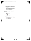
3WV
Type 1
(2-wire spring return)
Type 2
(3-wire SPST type)
Type 3
(3-wire SPDT type)
ORN
44
PNK
WHI
RED
4241
43
TB 04
MIXV
Type 1
(3-wire SPST type)
TB 05
MIXV
Type 2
(3-wire SPDT type)
1
3
2
1
3
2
Outdoor
unit
Power supply
230V
50Hz
21
Hot water cylinder
Power supply
230V
50Hz
*Option
Power supply
400V 3N
50Hz
HWS-1402XWHT9-E
Power supply
400V 3N
50Hz
Power supply
230V
50Hz
1
*
*
1
HWS-802XWHT6-E : Installed
HWS-1402XWHT6-E : Installed
HWS-1402XWHT9-E : Installed
HWS-802XWHM3-E : Not installed
HWS-1402XWHM3-E : Not installed
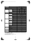
WPM
3WV
MIXV
2WV
LPS
Backup heater1,2,3
RY01 RY06
BH
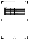
Parts name
Water pump motor
Low pressure sensor
Relay01 Relay06
Booster heater
3-way valve (local)
Heater AC230V, 3kW
2-way valve (local)
Mixing valve (local)
TB
TFI
TTW
THO
TWO
TWI
TC
Symbol
Water heat exchanger temperature sensor
Water heat exchanger inlet temperature sensor
Water heat exchanger outlet temperature sensor
Backup heater outlet temperature sensor
Hot water cylinder temperature sensor
Floor heating inlet temperature sensor
Terminal block
Parts name
2
3
4
1
3
4
2
1
3
4
1
2
GRN
GRN
GRN
GRN
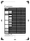
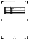
PJ20
Relay
p.c.board
(MCC-1217)
2
1
3
4
TB1
K1
K2
Boiler control O/P
Alerm O/P
Defrost O/P
Operation O/P
Relay
p.c.board
(MCC-1217)
PJ20
GRN
33
GRN
44
GRN
GRN
2
11
2
TB1
K2
K1
2
1
4
3
3
4
1
2
1
44
PJ17
TB1
Photocoupler input
p.c.board
(MCC-1214)
22
33
YEL
11
3
2
1
4
3
2
YEL
YEL
YEL
Heating thermostat I/P
Cooling thermostat I/P
Photocoupler input
p.c.board
(MCC-1214)
3
2
1
YEL
33
PJ17
44
YEL
YEL
YEL
11
22
1
TB1
3
2
Hot water cylinder
thermostat I/P
Emergency stop I/P
4
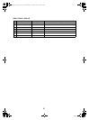
*Option p.c.board
WARNING
Perform the grounding from the
earth terminal in the terminal
block of the outdoor unit.
!
!
CAUTION
Electric shock may happen.
Don't touch the electric parts.
1. The one-dot chain line indicates wiring at the local site, and
the dashed line indicates accessories sold separately and
service wires, respectively.
2. , and indicates the terminal board and the numberals
indicate the terminal numbers.
3. indicates P.C. board.
* Be sure to fix the electric parts cover surely with screws.
(Otherwise water enters into the box resulting in malfunction.)
+00A09-002_01EN_SVM_ALL_Air_to_Water.book Page 21 Monday, October 5, 2009 2:09 PM