


137
Toshiba
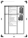
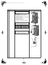
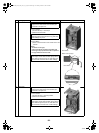
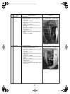
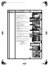
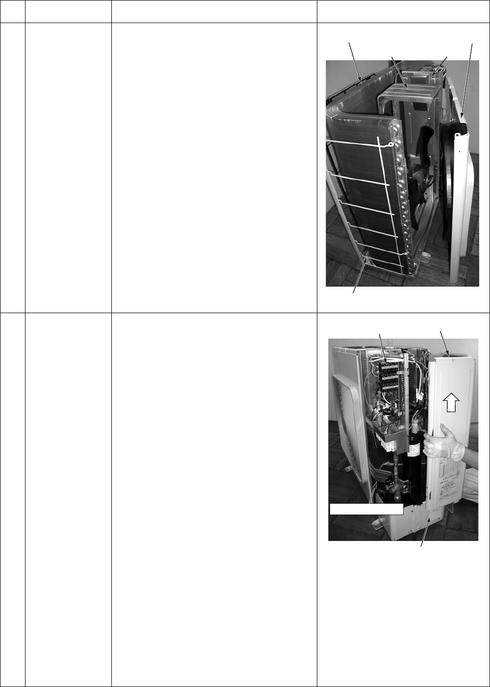
2 Outlet cabinet How to remove
1)Perform the step 1-1.
2)Remove the screws of the outlet cabinet and
parting board.
(ST1T Ø4 × 8, 3 screws)
3)Remove the screws of the outlet cabinet and
bottom board.
(Hex Ø4 × 10, 2 screws)
4)Remove the screws of the outlet cabinet and
motor base.
(ST1T Ø4 × 8, 2 screws)
5)Remove the screws of the outlet cabinet and water
heat exchanger.
(ST1T Ø4 × 8, 1 screw)
6)Remove the screws of the outlet cabinet and fin
guard.
(Hex Ø4 × 10, 2 screws)
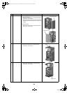
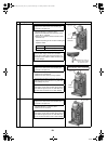
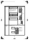
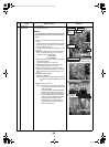
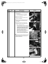
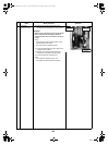
3 Side cabinet 1)Perform the step 1-1.
2)Remove the screws that fixes the inverter
assembly and the side cabinet.
(ST1T Ø4 × 8, 2 screws)
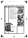
3)Remove the screws of the side cabinet and valve
fixing board.
(ST1T Ø4 × 8, 2 screws)
4)Remove the screws of the side cabinet and piping
panel (back).
(Hex Ø4 × 10, 2 screws)
5)Remove the screws of the side cabinet and bottom
board.
(Hex Ø4 × 10, 1 screw)
6)Remove the screws of the side cabinet and water
heat exchanger.
(Hex Ø4 × 10, 3 screws)
7)Remove the side cabinet while shifting it upward.
(Inverter hook)
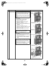
No.
Exchange parts
name
Work procedure Remarks
Outlet cabinet
Water heat exchanger
Motor base Paring board
Fin guard
Inverter assembly
Side cabinet
Piping panel (back)
Valve fixing board
+00A09-002_01EN_SVM_ALL_Air_to_Water.book Page 137 Monday, October 5, 2009 2:09 PM