


128
Toshiba
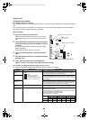
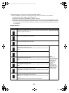
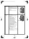
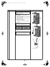
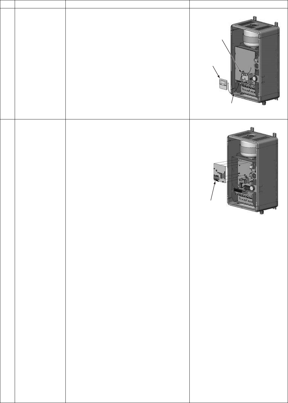
2 Remote controller 1.How to remove
1)Perform the step 1-1.
2)Remove the remote controller from the holder using
a flat-blade screwdriver. (Release the stopper.)
3)Disconnect the remote controller cable from the
terminal block on the back side of the remote
controller.
2.How to attach
1)Attach it in the reverse order of the removal.
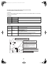
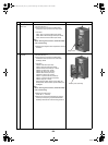
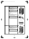
3 Water heat
exchanger board
MCC-1511
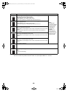
1.How to remove
1)Perform the step 1-1.
2)Disconnect the connectors and lead cables
connected to other parts from the water heat
exchanger board.
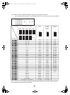
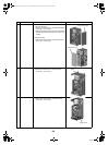
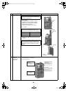
1.Connector
CN100: TB 01 3P Connector (5P: White)
CN101: Trans (3P: White)
CN102: Trans (6P: White)
CN200: Float switch (3P: Red)
CN201: Pressure switch (2P: White)
CN202: Bimetal thermostat (3P: Yellow)
CN203: TC sensor (2P: Yellow)
CN204: TWI sensor (3P: Brown)
CN205: TWO sensor (2P: Red)
CN206: THO sensor (3P: White)
CN207: Lo pressure sensor (2P: Blue)
CN212: Lo pressure sensor (4P: White)
CN213: TB 06 4P Terminal block (3P: White)
CN214: TB 06 4P Terminal block (2P: White)
CN305: TB 01 3P Terminal block (3P: Green)
CN501: Relay board (6P: Yellow)
CN601: Relay 05 (3P: Red)
CN602: TB 04 6P Terminal block (7P: White)
CN603: Pump (3P: Yellow)
CN604: Relay 06, TB 04 4P Terminal block (7P:
Blue)
CN605: Relay 01, Relay 02 (3P: Yellow)
CN606: Relay 03, Relay 04 (3P: Blue)
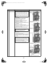
2.Round-shape terminal
100: Ground (ST2T Ø4 × 8 1 wire)
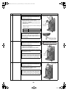
Note
When removing the connector, release the safety
lock of the housing.
3)Release the 6 stoppers of the water heat exchanger
board to remove the board.
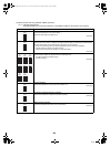
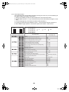
No.
Exchange parts name
Work procedure Remarks
Remote
controller holder
Remote
controller
Remote controller cable
Water heat
exchanger board
+00A09-002_01EN_SVM_ALL_Air_to_Water.book Page 128 Monday, October 5, 2009 2:09 PM