


135
Toshiba
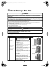
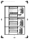
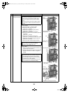
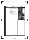
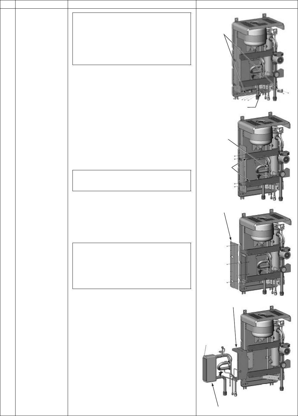
17 Water heat
exchanger assembly
1.How to remove
1)Perform the step 1-1, step 5, 6, and 8.
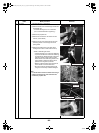
2)Remove the water pipe fixing board.
(ST2T Ø4 × 8, 2 screws)
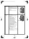
3)Remove the refrigerant piping fixing board.
(ST2T Ø4 × 8, 3 screws)
4)Remove the nut of the heater connection.
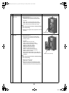
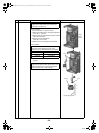
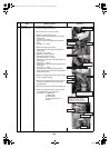
5)Remove the fixed screws of the electric parts box
fixing board.
(ST2T Ø4 × 8, 4 screws)
6)Remove the side reinforcing board (left).
(ST2T Ø4 × 8, 6 screws) 3 for inside, 3 for outside
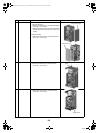
7)Remove the water heat exchanger fixing band.
(ST2T Ø4 × 8, 6 screws)
8)Remove the water heat exchanger assembly.
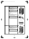
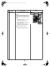
2.How to attach
1)Attach a new water heat exchanger assembly in the
reverse order of the removal.
2)Restore all piping and wiring as in the original state,
and check that there is no water or refrigerant
leakage.
No.
Exchange parts name
Work procedure Remarks
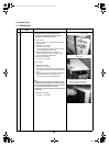
• Close the water piping source valve and the valve
of water pipe connected to the hydro unit, and
then remove the refrigerant and water piping.
• Perform refrigerant recovery with the outdoor
unit.
• Disconnect all the power source cable, outdoor
unit connection cable, and cylinder connection
cable.
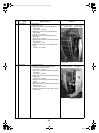
The heater connection uses a packing for water
seal. Be careful not to scratch the packing;
otherwise, water leakage may occur.
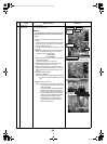
• After the water heat exchanger assembly
replacement repair, open the water supply source
valve and water piping source valve to pass
water through the hydro unit, and check that the
connection has no water leakage.
• After connecting the refrigerant pipe, check that
the connection has no refrigerant leakage.
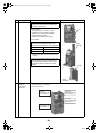
Water
piping fixing
Refrigerant piping
fixing board
Nut
Electric parts
box fixing
Side reinforcing board (left)
Water heat exchanger assembly
Water heat exchanger
fixing band
The piping
structure slightly
differs in 14kW and
8kW specifications.
+00A09-002_01EN_SVM_ALL_Air_to_Water.book Page 135 Monday, October 5, 2009 2:09 PM