


151
Toshiba
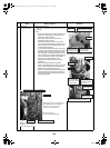
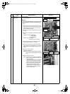
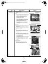
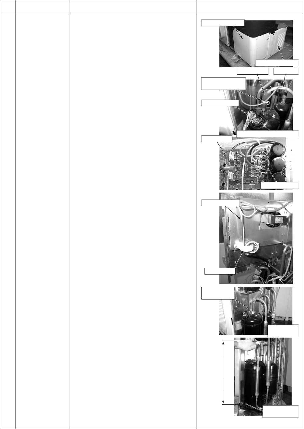
6 Compressor
Compressor lead
1.Remove defective compressor
1)Perform refrigerant gas recovery.
2)Perform the step 1-1 and step 3.
3) Remove the piping panel (Front).
Remove screws of the piping panel (Front) and
bottom board.
(Hex Ø4 × 10, 2 screws)
Remove screws of the piping panel (Front and
Back).
(Hex Ø4 × 10, 1 screws)
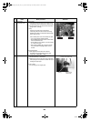
4)Remove the piping panel (Back).
Remove screws of the piping panel (Back) and
bottom board.
(Hex Ø4 × 10, 2 screws)
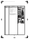
5)Remove the soundproofing board. (Upper, Inward
winding, Outward winding)
6)Remove the compressor terminal cover, and then
remove the compressor lead and compressor
case thermostat.
7)Remove the TD sensor fixed to the discharge
piping.
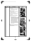
8)Remove the compressor lead. (Leave the ferrite
core attached to the electric parts box.)
Control board U: CN200 Red
V: CN201 White
W: CN202 Black
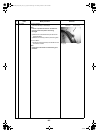
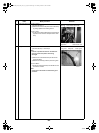
9)Remove the outlet and suction pipes connected to
the compressor by using a burner.
WARNING
When removing the piping by burning the solder,
take enough care for a fire going off at the
moment the wax melts if oil remains inside the
piping.
Note)
Do not make fire flame contact with the 4-way
valve and pulse motor valve.
(This may cause an operation failure.)
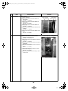
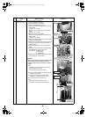
10) Pull out the discharge and suction pipes of the
refrigerant cycle upward.
11) Remove the compressor nuts that fix the
compressor to the bottom board. (3 nuts)
12) Pull the compressor out toward you.
Note)
The compressor weighs 20 kg or more.
Two people should be required to handle it.
No.
Exchange parts
name
Work procedure Remarks
Piping panel (Front)
Piping panel (Back)
450
TD sensor
Piping cover
Binding tie
(for heat resistance)
Remove
(Outlet pipe)
Compressor nut
(3 nuts)
Remove
(Suction pipe)
Compressor case thermostat
Compressor lead
Compressor lead
Compressor lead
Ferrite core
Control board
+00A09-002_01EN_SVM_ALL_Air_to_Water.book Page 151 Monday, October 5, 2009 2:09 PM