


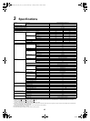
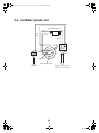
19
Toshiba
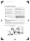
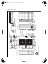
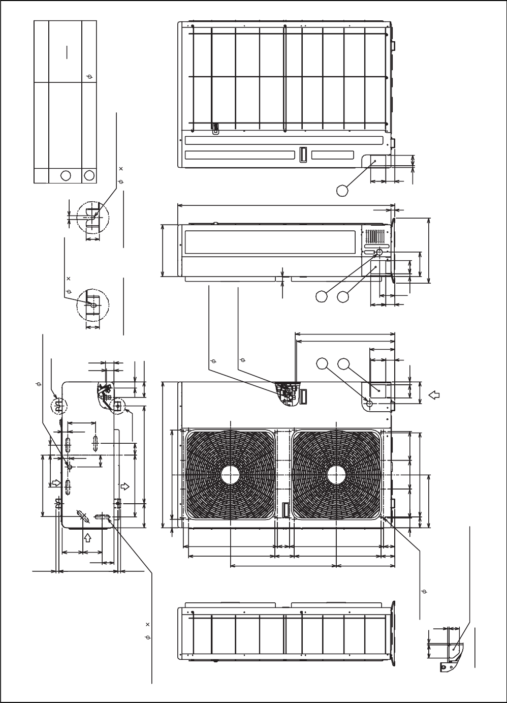
HWS-1102H-E, 1402H-E
Portion B
96
39
48
54
600
Portion A
70
34
75
46
170
60
380
200
17.5
128
Air inlet
118
74
383
Air outlet
150
17.5 365
Mounting bolt hole
Power source intake hole
Mounting bolt hole
Details of portion A
40
40
Details of portion B
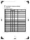
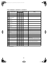
12
2
1
Description
38 knockout hole
Name
65
83
Knockout for lower part of piping
Z arrow view
Z
Refrigerant gas connection
Refrigerant liquid connection
1
2
1
2
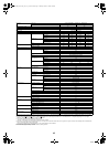
9555
12
64
1
1340
320
30
55
95
94
18
80
151
400
24
55
95
1880
135
155
613
605
900
70 581 74 581
178 178 178
518
52 550
360 655
327
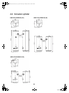
Optional mounting hole
(24- 3 embossed)
60
68
53412153485
7
7
Drain hole ( 25 burring hole)
5-Drain hole ( 20 88 burring hole)
Air inlet
( 12 17 long hole)
( 12 17 U-shape hole)
Refrigerant piping outlet
Indoor and outdoor
connecting line outlet
( 9.5 flare)
( 15.9 flare)
+00A09-002_01EN_SVM_ALL_Air_to_Water.book Page 19 Monday, October 5, 2009 2:09 PM