


22
Toshiba
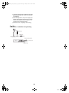
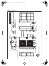
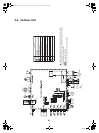
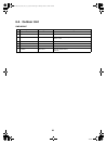
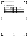
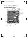
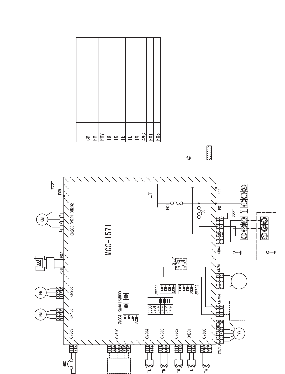
5-2. Outdoor Unit
Control board
(Blue)
(
White)
HMS-1102,
1402H-E only
(White)
(
White)
Upper
(White)
Operating
power
4-way
valve
coil
Reactor
230V
50Hz
Earth screw
Earth screw
Earth
screw
Hydro unit
Outdoor unit
Power supply
single phase
(Yellow)
(
White)
(
White)
(
Yellow)
(
White)
(
White)(White)(White)
(
White)
WR B
WhiteRed
G
RWB
External
input
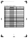
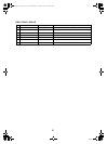
Symbol Item nam
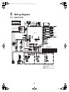
Compressor
Fan motor
Pulse motor valve coil
Discharge temperature sonsor
Suction temperature sensor
Heat exchange sensor 1
Heat exchange sensor 2
Outdoor temperature sensor
Compressor case thermostat
Fuse 25 A, 250 VAC
Fuse 10A, 250 VAC
1. indicates a terminal plate. The number inside indicates the terminal number.
2. The double-dashed line indicates a local wiring while the dashed line indicates
an optional accessory or service wiring.
3. indicates a printed board.
4. For the hydro unit circuit, see the hydro unit wiring diagram.
+00A09-002_01EN_SVM_ALL_Air_to_Water.book Page 22 Monday, October 5, 2009 2:09 PM