


130
Toshiba
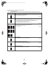
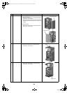
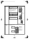
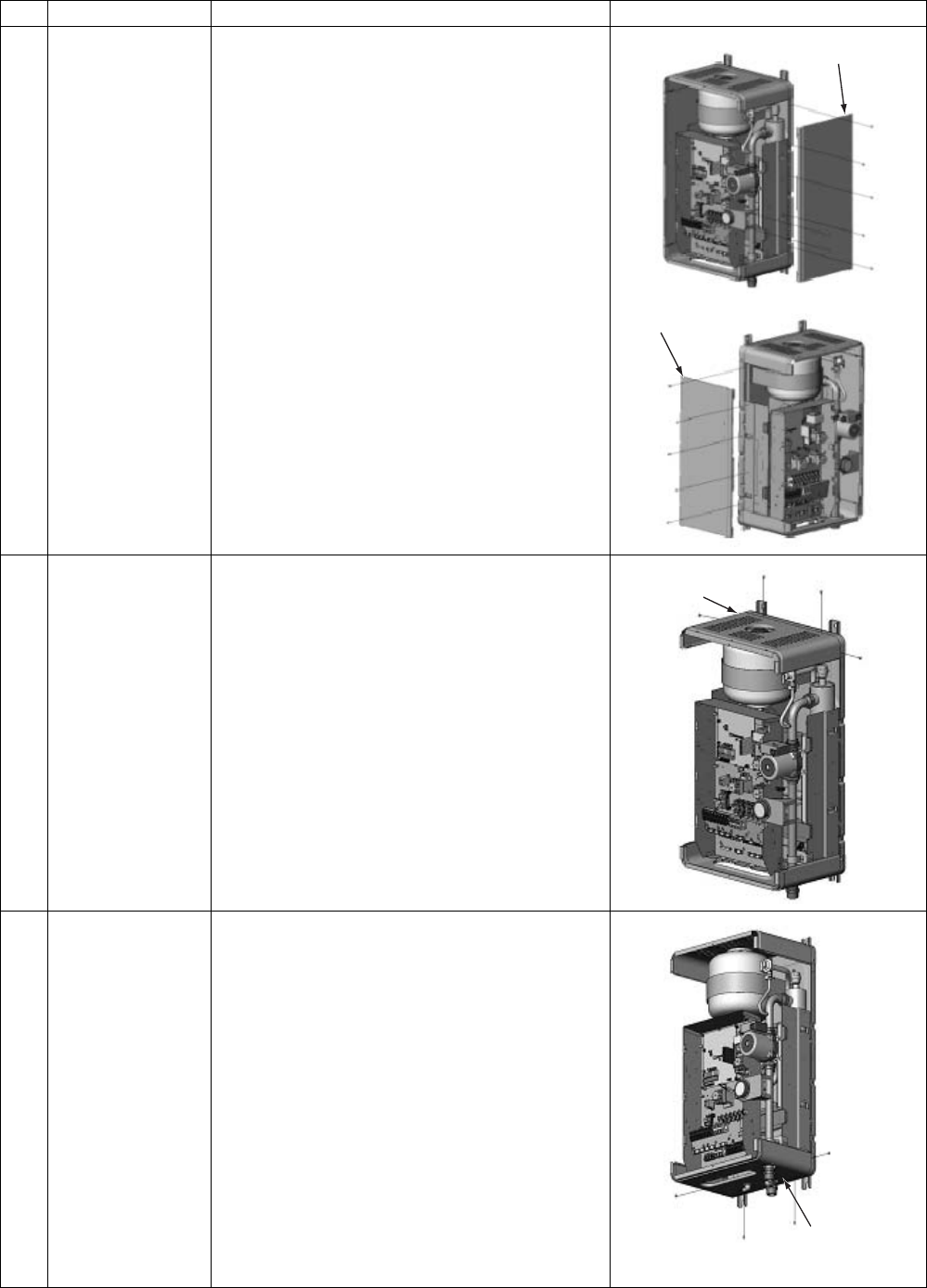
6 Side board 1.Side board (Right)
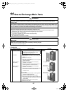
1)Perform the step 1-1.
2)Remove the fixed screws of the side board (Right).
(ST1T Ø4 × 10, 5 screws)
3)Remove the fixed screws of the side board (Right)
and the manometer fixing board. (ST1T Ø4 × 10, 2
screws)
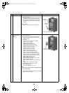
2.Side board (Left)
1)Remove the fixed screws of the side board (Left).
(ST1T Ø4 × 10, 5 screws)
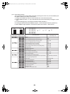
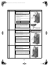
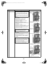
7 Upper board 1)Perform the step 1-1 and step 6.
2)Remove the fixed screws of the upper board.
(ST1T Ø4 × 10, 4 screws)
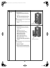
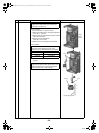
8 Bottom board 1)Perform the step 1-1 and step 6.
2)Remove the fixed screws of the bottom board.
(ST1T Ø4 × 10, 4 screws)
No.
Exchange parts name
Work procedure Remarks
Side board (Right)
Side board (Left)
Upper
Bottom board
+00A09-002_01EN_SVM_ALL_Air_to_Water.book Page 130 Monday, October 5, 2009 2:09 PM