


148
Toshiba
4 Electric parts
replacement
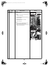
1.Control board
1)Perform the step 1-1.
WARNING
For 1 minute after the power is turned off, do not
disassemble the inverter to prevent an electric
shock.
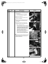
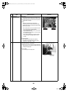
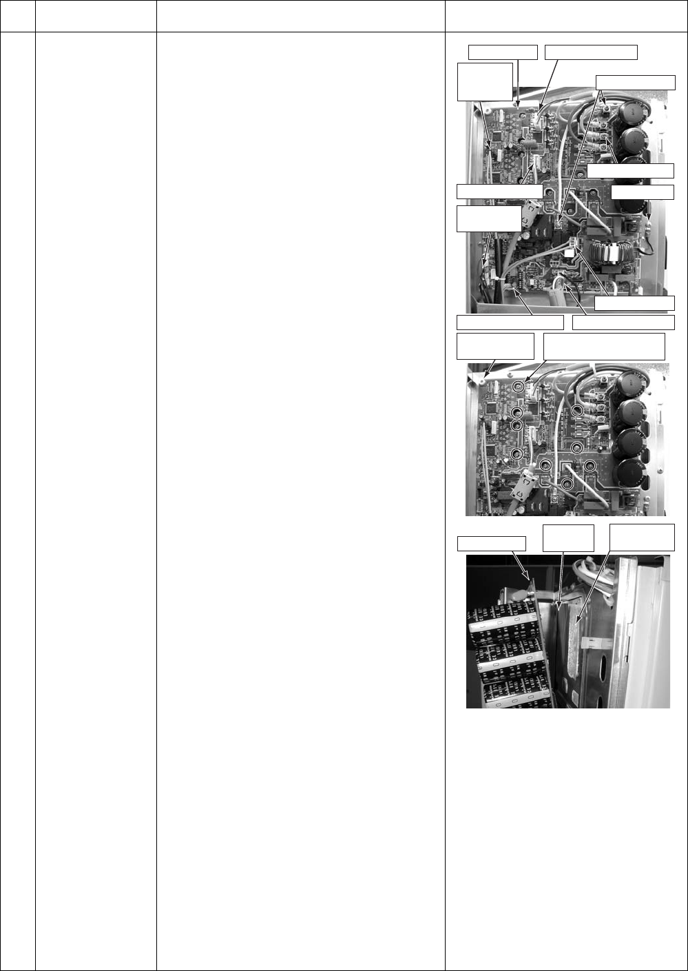
2)Remove the connector connected to the control
(Hydro power source, temperature sensor, electric
control valve coil, 4-way valve coil, compressor
case thermostat, fan motor)
* Remove the connector by releasing the lock in the
housing.
3)Remove the lead cable connected to the control
board.
Compressor lead U: CN200 Red
V: CN201 White
W: CN202 Black
Reactor lead CN05 White
CN06 White Relay connector
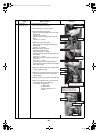
4)Remove the ground wire of the control board.
(Truss B tight screw Ø4 × 6, 1 screw)
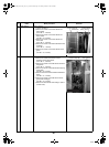
5)Remove the fixed screws of the control board.
(Collar screw for fixing element Ø3 × 16, 9 screws,
Pan S-tight screw for fixing the board Ø3 × 20, 1
screw)
6)Remove the control board.
(Supporter 5 positions)
Note) Removing the control board may be difficult
due to the heat release grease for the heat
sink.
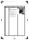
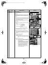
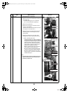
7)Attach a new control board.
Note) • Be careful for not taking the compressor
lead V: CN201 White for the reactor lead
CN05 or 06 White.
(The compressor lead has a transparent
sleeve at its ring terminal. The reactor
lead ring terminal does not have sleeve.)
• Be sure to attach the insulating sheet.
(Applying beforehand a bit of heat
release grease to the back side of the
insulating sheet can easily paste the
sheet to the heat sink.)
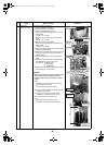
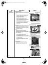
No.
Exchange parts
name
Work procedure Remarks
Control board
Control board
Insulating
sheet
Hear release
grease
Fan motor (upper)
Fan motor (lower)
Reactor lead
Compressor lead
4-way valve coil
Temperature
sensor
Indoor power sourceMotorized control coil
Screw for fixing
board
Screw for fixing element
(9 positions)
Ground wire
Compressor
case
thermostat
+00A09-002_01EN_SVM_ALL_Air_to_Water.book Page 148 Monday, October 5, 2009 2:09 PM