


143
Toshiba
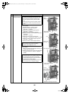
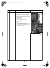
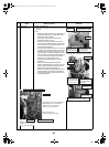
6 Compressor
Compressor lead
2.Attach the compressor
1)Attach the compressor in the reverse order of the
removal.
Note)
• Be sure to replace the compressor lead after the
compressor replacement. (Compressor lead
spare parts code: 43160591)
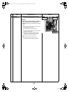
At this time, wind the ferrite core with the
compressor lead for 4 times.
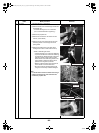
Bind the compressor lead that is long with a
commercially available binding tie. When doing
this, be careful for the compressor lead not to
contact the discharge pipe.
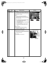
• Fix the removed sensors and pulse motor valve
coil lead to the outlet and suction pipes through
the piping cover by using a binding tie. At this
time, be careful for the sensors and pulse motor
valve coil lead not to contact the discharge pipe.
(To fix the sensors and leads, use the black
piping cover for heat resistance and a
commercially available binding tie for heat
resistance.)
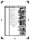
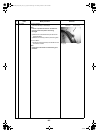
• Attach the soundproofing board (Inward
winding, Outward winding), as shown in the right
figure, through between the compressor and
between the piping and parting board.
• Place the compressor lead and the compressor
case thermostat so that they fall into between
the inward winding and outward winding of the
soundproofing board.
No.
Exchange parts
name
Work procedure Remarks
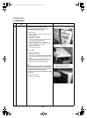
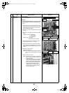
Black piping cover for heat resistance,
and Binding tie for heat resistance
Sensors (TL, TO, TE, TD, TS)
Pulse motor valve coil lead
Piping cover, Binding tie
Sensors (TL, TO, TE, TS)
Pulse motor valve coil lead
Keep sensors away
for not contacting outlet pipe
Pulse motor valve coil leadSuction pipe
Piping cover, Binding tie, TS sensor
Outlet pipe
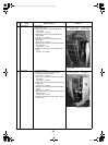
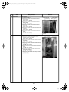
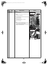
Place soundproofing board (Outward winding)
through between suction pipe and accumulator
Compressor
lead
Ferrite core
Suction pipe
Accumulator
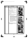
Soundproofing
board (Upper)
Soundproofing board
(Outward winding)
Do not make gap between soundproofing
boards (Upper and Outward winding)
Header pipe
Overlap soundproofing
board (Outward winding)
at this position
Place soundproofing
board (Inward winding)
through between suction
pipe and header pipe
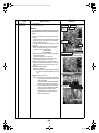
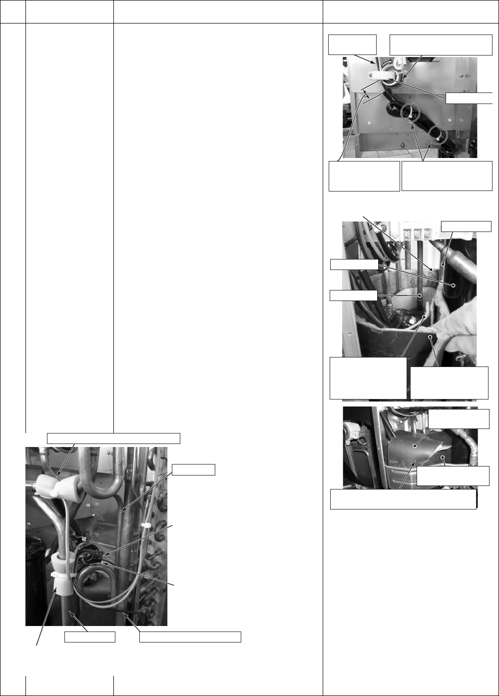
0 to 50
(Compressor lead
positioning standard)
Bind the lead at 2 positions
with a commercially
available binding tie
Wind ferrite core with
compressor lead for 4 times.
+00A09-002_01EN_SVM_ALL_Air_to_Water.book Page 143 Monday, October 5, 2009 2:09 PM