


150
Toshiba
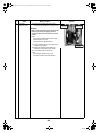
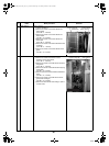
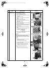
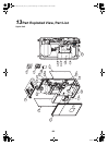
5 Fan motor 1)Perform the step 1-1 and step 2.
2)Remove the fan motor and the flange nut that fixes
the propeller fan.
• To loosen the flange nut, turn it clockwise.
(Turn it counterclockwise for tightening.)
3)Remove the propeller fan.
4)Remove the connector for fan motor from the
inverter. (control board)
(Remove the ferrite core of the lower fan motor to
use it again for a new fan motor.)
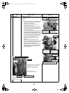
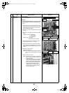
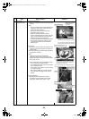
5)Remove the fan motor lead from the fan motor
lead fixing rubber on the through hole of the
parting board.
6)Remove the fixed screws (4 for each) while
holding the fan motor so that it does not drop.
* Notes in assembling fan motor
• Tighten the flange nut in 4.95 N•m (50kgf•cm).
• To prevent the fan motor lead from contacting
the propeller fan, adjust the length of fan motor
lead fixing rubber so that it does not slack.
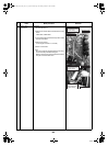
Attach the fan motor lead fixing rubber to the
parting board so that the projection part is
placed on the refrigerant cycle side.
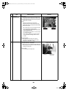
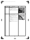
• Make sure that the reactor body and the fan
motor lead do not contact each other.
• Be sure to bind the removed binding tie by
using the commercially available binding tie.
• Be sure to re-attach the ferrite core of the
lower fan motor. (Fix this with a commercially
available binding tie.)
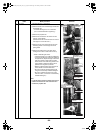
Note
Fix the fan motor lead to the motor base using a
metal tie so that the fan motor lead does not
contact the propeller fan.
No.
Exchange parts
name
Work procedure Remarks
Propeller fan
Fan motor ferrite
core (lower)
Fan motor
connector (upper)
Fan motor
connector (lower)
Fan motor lead
fixing rubber
Fan motor lead
fixing rubber
Fan motor
Fan motor
Turn it right
to loosen
Flange nut
Propeller fan
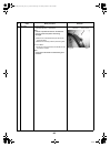
Projection/Refrigerant
cycle side
Projection/Refrigerant
cycle side
+00A09-002_01EN_SVM_ALL_Air_to_Water.book Page 150 Monday, October 5, 2009 2:09 PM