


59
Toshiba
8-4.
Outdoor unit
control
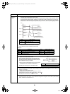
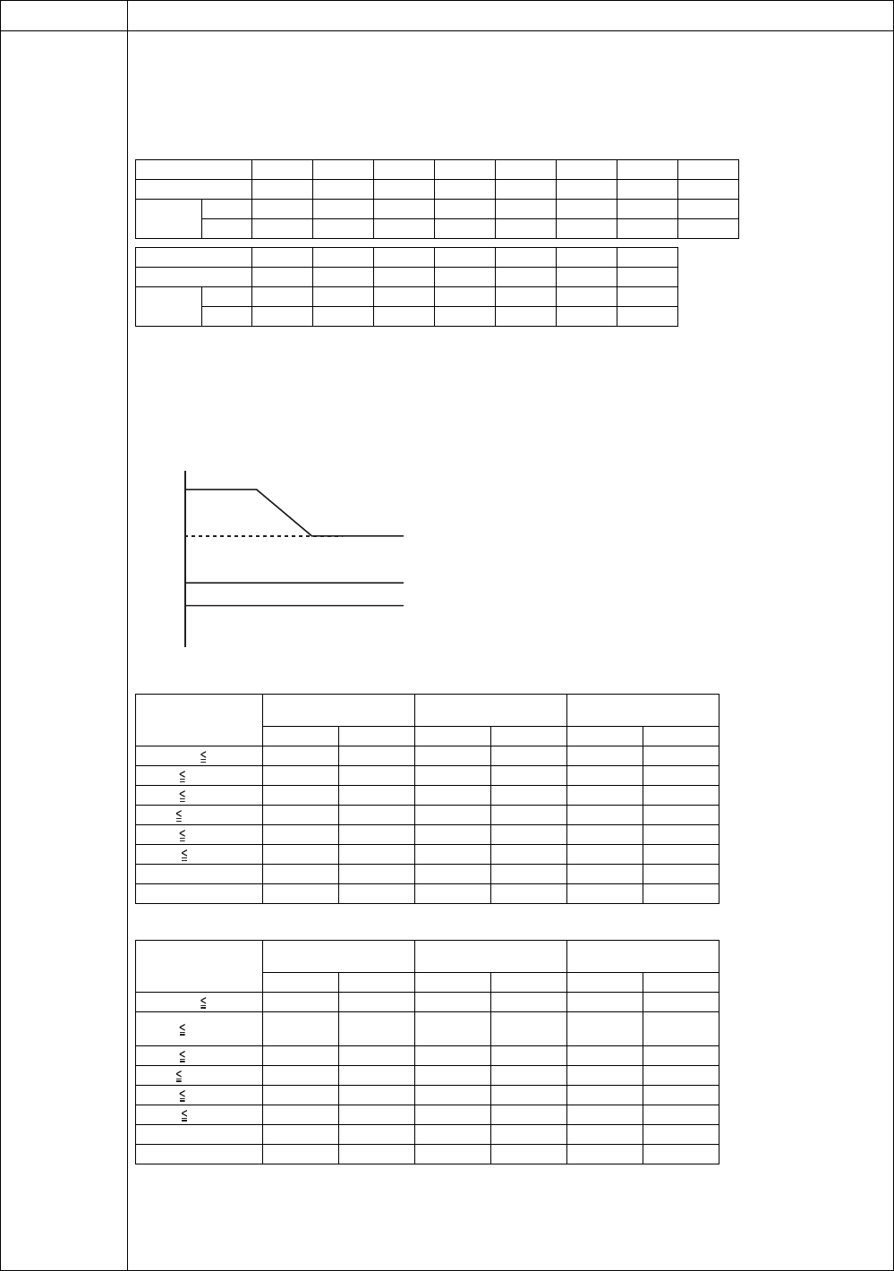
5)Outdoor fan control
The outdoor side control part controls the number of fan motor rotations by receiving an operation instruction from the
indoor side (Hydro unit) control part.
* Although the fan motor is a DC motor, which has non-step variable numbers of rotations, it is limited to some steps for convenience of
control.
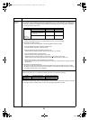
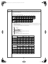
The number of fan tap rotation allocation [rpm]
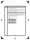
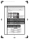
5-1)Cooling fan control
• The TL sensor, TO sensor and operation frequency control the outdoor fan. The control is performed by 1 tap of
the DC fan control (14 taps).
• For 60 seconds after the start, the maximum fan tap for each zone that is shown in the following table is fixed. After
that, the fan is controlled according to the TL sensor temperature.
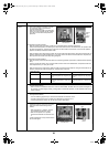
HWS-802H-E
HWS-1102H-E, 1402H-E
Item Operation flow and applicable data, etc.
W1 W2 W3 W4 W5 W6 W7 W8
802H-E 200 230 260 300 340 380 420 460
1102,
1402H-E
Upper 200 240 240 260 320 380 480 500
Lower 200 200 200 280 360 400 500 520
W9 WA WB WC WD WE WF
802H-E 520 570 600 630 670 710 740
1102,
1402H-E
Upper 530 610 640 660 720 780 890
Lower 550 630 660 700 740 820 910
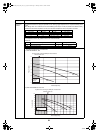
TL [
°C
]
58
55
38
35
WE tap
+ 1 tap/20 secs
(Up to the maximum number of rotation for each zone)
- 1 tap/20 secs
(Up to the minimum number of rotation for each zone)
Number of rotation hold
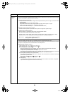
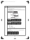
Temperature range
Less than 20 Hz
20 Hz or more to less
than 45 Hz
45 Hz or more
Minimum Maximum Minimum Maximum Minimum Maximum
38°C TO W6 WC W8 WE WA WE
29°C TO < 38°C W5 WB W7 WD W9 WD
15°C TO < 29°C W4 W8 W6 WA W8 WC
5°C TO < 15°C W3 W6 W5 W8 W7 WA
0°C TO < 5°C W2 W4 W4 W6 W5 W8
-4°C TO < 0°CW2W3W3W5W4W6
TO < -4°C OFF OFF OFF W2 OFF W3
TO abnormal OFF WC OFF WE OFF WE
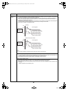
Temperature range
Less than 20 Hz
20 Hz or more to less
than 45 Hz
45 Hz or more
Minimum Maximum Minimum Maximum Minimum Maximum
38°C TO W6 WC W8 WC WA WD
29°C TO < 38°C W5 WB W7
WC
(WB for 1102)
W9 WC
15°C TO < 29°C W4 W8 W6 WA W8 WC
5°C TO < 15°C W3 W6 W5 W8 W7 WA
0°C TO < 5°C W2 W4 W4 W6 W5 W8
-4°C TO < 0°CW2W3W3W5W4W6
TO < -4°C W1W2W1W4W2W6
TO abnormal W1 WC W1 WC W2 WD
+00A09-002_01EN_SVM_ALL_Air_to_Water.book Page 59 Monday, October 5, 2009 2:09 PM