


141
Toshiba
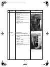
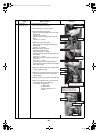
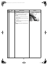
6 Compressor
Compressor lead
1.Remove defective compressor
1)Perform refrigerant gas recovery.
2)Perform the step 1-1 and step 2 and 3.
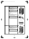
3)Remove the piping panel (Front).
Remove screws of the piping panel (Front) and
bottom board.
(Hex Ø4 × 10, 2 screws)
Remove screws of the piping panel (Front and
Back).
(Hex Ø4 × 10, 1 screw)
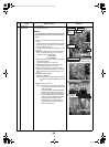
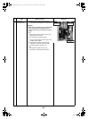
4)Remove the piping panel (Back).
Remove screws of the piping panel (Back) and
bottom board.
(Hex Ø4 × 10, 2 screws)
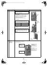
5)Remove the valve fixing board.
Remove the bolt of the valve.
(Hex head bolt Ø6 × 15, 4 bolts)
Remove the screws of the valve fixing board and
parting board.
(ST1T Ø4 × 8, 1 screw)
Remove the screws of the valve fixing board and
accumulator.
(ST1T Ø4 × 8, 1 screw)
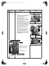
Cut the binding tie of the discharge pipe and
suction pipe to remove each sensor and the pulse
motor valve coil lead.
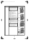
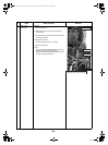
6)Remove the soundproofing board. (Upper, Inward
winding, Outward winding)
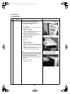
7)Remove the compressor terminal cover, and then
remove the compressor lead and compressor
case thermostat.
8)Remove the TD sensor fixed to the discharge pipe.
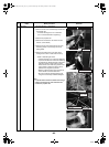
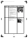
9)Remove the compressor lead. (Leave the ferrite
core attached to the electric parts box.)
Control board U: CN200 Red
V: CN201 White
W: CN202 Black
(Torque at tightening is 1.47
±0.1N•m)
No.
Exchange parts
name
Work procedure Remarks
Piping panel (Back)
Piping panel (Front)
TD sensor
Pipe cover
Binding tie for
heat resistance
Compressor case
thermostat
Compressor lead
TS sensor
Outlet pipe
Pipe cover, Binding tie
Pipe cover, Binding tie
Sensors (TL, TO, TE, TS)
Motorized control valve coil lead
Black pipe cover for heat resistance,
Binding tie for heat resistance
Sensors (TL, TO, TE, TD, TS)
Motorized control valve coil lead
Suction pipe
Accumulator
Compressor lead
Control board
Ferrite core
Compressor lead
+00A09-002_01EN_SVM_ALL_Air_to_Water.book Page 141 Monday, October 5, 2009 2:09 PM