


133
Toshiba
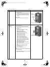
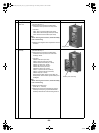
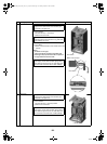
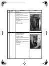
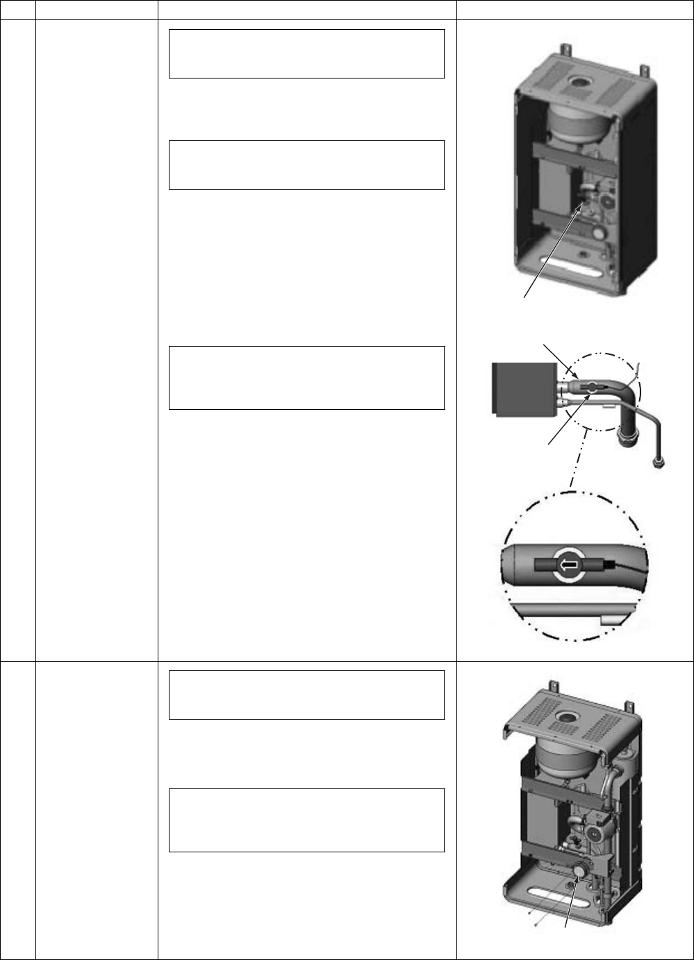
13 Flow switch
1.How to remove
1)Perform the step 1-1 and step 5.
2)Remove the flow switch.
2.How to attach
1)Attach a new flow switch in the reverse order of the
removal.
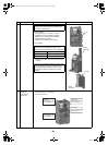
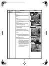
Note1)
As shown on the right,
place a flow sensor parallel to the water heat
exchanger inlet pipe so that the wire is place on
the right side from the front view.
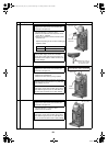
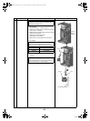
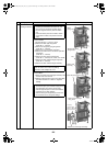
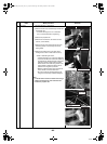
14 Manometer
1.How to remove
1)Perform the step 1-1 and step 5 and 6.
2)Remove the manometer.
No.
Exchange parts name
Work procedure Remarks
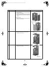
To replace a water circuit part, first close the water
supply source valve and the valve of water pipe
connected to the hydro unit.
The flow switch connection uses an O ring for water
seal. Be careful not to scratch the O ring; otherwise,
water leakage may occur.
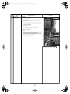
After the flow switch replacement repair, open the
water supply source valve and water piping valve to
pass water through the hydro unit, and check that
the flow switch connection has no water leakage.
Flow switch
Flow switch
Water heat inlet pipe
To replace a water circuit part, first close the water
supply source valve and the valve of water pipe
connected to the hydro unit.
After the manometer replacement repair, open the
water supply source valve and water piping valve to
pass water through the hydro unit, and check that
the manometer connection has no water leakage.
Manometer
+00A09-002_01EN_SVM_ALL_Air_to_Water.book Page 133 Monday, October 5, 2009 2:09 PM