


Optional Hardware and Software Teledyne API – Technical Manual - Model 300E Family CO Analyzers
78
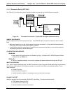
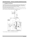
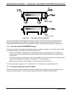
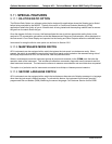
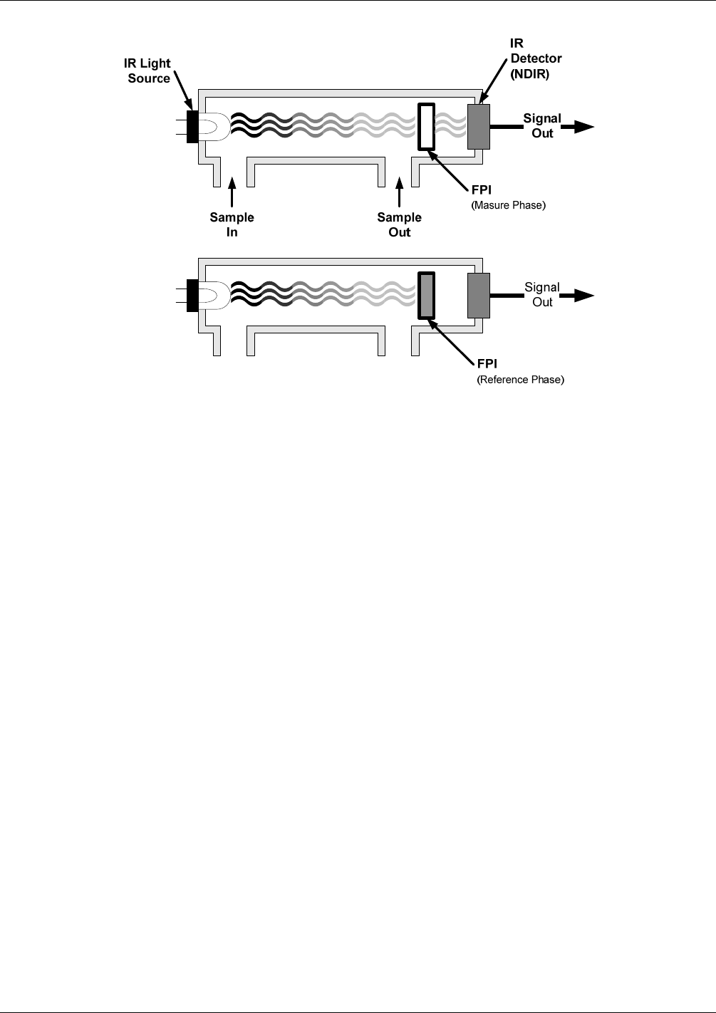
Figure 5-16: CO
2
sensor Theory of Operation
The sensor computes the ratio between the reference signal and the measurement signal to determine the
degree of light absorbed by CO
2
present in the sensor chamber. This dual wavelength method the CO
2
measurement allows the instrument to compensate for ancillary effects like sensor aging and contamination.
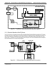
5.9.2.2. Operation within the M300E/EM Analyzer
The CO
2
sensor option is transparently integrated into the core analyzer operation. All functions can be viewed
or accessed through the front panel, just like the functions for CO.
The CO
2
concentration is displayed in the upper right-hand corner, alternating with CO concentration.
Test functions for CO
2
slope and offset are viewable from the front panel along with the analyzer’s other
test functions.
CO
2
sensor calibration is performed via the front panel CAL function and is performed in a nearly identical
manner as the standard CO calibration. See Section 9.7.2 for more details.
Stability of th
e CO
2
sensor can be viewed via the front panel (see Section 9.7.2.3).
The CO
2
concentration range is 0-20%. See Section 9.7.2.1 for information on calibrating the CO
2
.
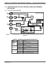
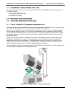
5.9.2.3. Pneumatic Operation of the CO
2
Sensor
Pneumatically, the CO
2
sensor is placed in line with the sample gas line between the particulate filter and the
analyzer’s sample chamber. It does not alter the gas flow rate of the sample through the analyzer.
04288D DCN5752