Teledyne API – Technical Manual - Model 300E Family CO Analyzers Theory of Operation
233
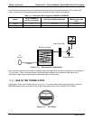
Interference and Signal to Noise Rejection:
If an interfering gas, such as H
2
O vapor is introduced into the sample chamber, the spectrum of the IR beam is
changed in a way that is identical for both the reference and the measurement cells, but without changing the
ratio between the peak heights of CO MEAS and CO REF. In effect, the difference between the peak heights
remains the same.
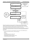
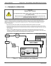
IR shining through both cells is
affected equally by interfering
gas in the Sample Chamber
M/R
is Shifted
Figure 11-5: Effects of Interfering Gas on CO MEAS & CO REF
Thus, the difference in the peak heights and the resulting M/R ratio is only due to CO and not to interfering
gases. In this case, GFC rejects the effects of interfering gases and so that the analyzer responds only to the
presence of CO.
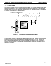
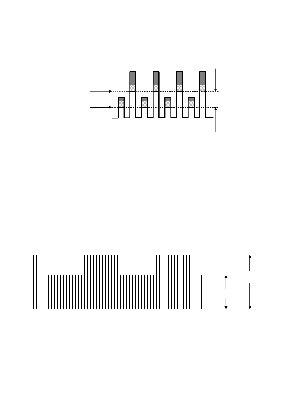
To improve the signal-to-noise performance of the IR photo-detector, the GFC Wheel also incorporates an
optical mask that chops the IR beam into alternating pulses of light and dark at six times the frequency of the
measure/reference signal. This limits the detection bandwidth helping to reject interfering signals from outside
this bandwidth improving the signal to noise ratio.
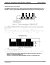
The IR Signal as the Photo-
Detector sees it after being
chopped by the GFC Wheel
S
CO REF
CO MEAS
Figure 11-6: Chopped IR Signal
11.2.1.3. Summary Interference Rejection
The basic design of the M300E/EM rejects most of this interference at a 300:1 ratio. The two primary methods
used to accomplish this are:
The 4.7μm band pass filter just before the IR sensor which allows the instrument to only react to IR
absorption in the wavelength affected by CO.
Comparison of the measure and reference signals and extraction of the ratio between them.
04288D DCN5752


