


Teledyne API – Technical Manual - Model 300E Family CO Analyzers Theory of Operation
245
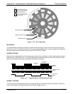
11.5.4.6. Electric Test Switch
When active, this circuit generates a specific waveform intended to simulate the function of the IR photo-detector
but with a known set of value which is substituted for the detector’s actual signal via the dark switch. It may also
be initiated by the user (See Section 7.4 for more details).
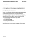
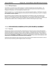
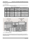
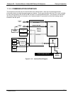
11.5.5. RELAY BOARD
By actuating various switches and relays located on this board, the CPU controls the status of other key
components. The relay board receives instructions in the form of digital signals over the I
2
C bus, interprets these
digital instructions and activates its various switches and relays appropriately.
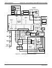
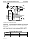
11.5.5.1. Heater Control
The two heaters attached to the sample chamber housing and the GFC Wheel motor are controlled by solid state
relays located on the relay board.
The GFC Wheel heater is simply turned on or off, however control of the bench heater also includes circuitry that
selects which one of its two separate heating elements is activated depending on whether the instrument is
running on 100 VAC, 115 VAC or 230 VAC line power.
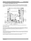
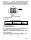
11.5.5.2. GFC Wheel Motor Control:
The GFC Wheel operates from a AC voltage supplied by a multi-input transformer located on the relay board.
The step-down ratio of this transformer is controlled by factory-installed jumpers to adjust for 100 VAC, 115 VAC
or 230 VAC line power. Other circuitry slightly alters the phase of the AC power supplied to the motor during
start up based on whether line power is 50Hz or 60 Hz.
Normally, the GFC Wheel Motor is always turning while the analyzer is on. A physical switch located on the
relay board can be used to turn the motor off for certain diagnostic procedures.
11.5.5.3. Zero/Span Valve Options
Any zero/span/shutoff valve options installed in the analyzer are controlled by a set of electronic switches located
on the relay board. These switches, under CPU control, supply the +12VDC needed to activate each valve’s
solenoid.
11.5.5.4. IR Source
The relay board supplies a constant 11.5VDC to the IR Source. Under normal operation the IR source is always
on.
04288D DCN5752