Teledyne API –Operation Manual - Model 300E Family CO Analyzers Table of Contents
xi
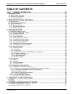
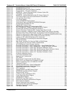
6.6. SETUP RNGE: Analog Output Reporting Range Configuration ..............................................................97
6.6.1. Physical Range versus Analog Output Reporting Ranges ....................................................................97
6.6.2. Analog Output Ranges for CO Concentration .......................................................................................98
6.6.3. Reporting Range Modes........................................................................................................................99
6.6.3.1. RNGE MODE SNGL: Configuring the M300E/EM Analyzer for SINGLE Range Mode..... 100
6.6.3.2. RNGE MODE DUAL: Configuring the M300E/EM Analyzer for DUAL Range Mode ........ 101
6.6.3.3. RNGE MODE AUTO: Configuring the M300E/EM Analyzer for AUTO Range Mode........ 103
6.6.4. SETUP RNGE UNIT: Setting the Reporting Range Units of Measure...................................... 104
6.6.5. SETUP RNGE DIL: Using the Optional Dilution Ratio Feature.................................................. 105
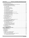
7. ADVANCED FEATURES ................................................................................................. 107
7.1. SETUP IDAS: Using the Data Acquisition System (iDAS) .................................................................... 107
7.1.1. IDAS Status ........................................................................................................................................ 107
7.1.2. IDAS Structure .................................................................................................................................... 108
7.1.2.1. iDAS Channels ............................................................................................................................ 108
7.1.3. Default iDAS Channels ....................................................................................................................... 109
7.1.4. SETUP DAS VIEW: Viewing iDAS Channels and Individual Records ....................................... 111
7.1.5. SETUP DAS EDIT: Accessing the iDAS Edit Mode ................................................................... 112
7.1.5.1. Editing iDAS Data Channel Names............................................................................................. 113
7.1.5.2. Editing iDAS Triggering Events................................................................................................... 114
7.1.5.3. Editing iDAS Parameters............................................................................................................. 115
7.1.5.4. Editing Sample Period and Report Period................................................................................... 117
7.1.5.5. Report Periods in Progress When Instrument Is Powered Off.................................................... 118
7.1.5.6. Editing the Number of Records ................................................................................................... 119
7.1.5.7. RS-232 Report Function.............................................................................................................. 120
7.1.5.8. Enabling/Disabling the HOLDOFF Feature................................................................................. 121
7.1.5.9. The Compact Report Feature...................................................................................................... 122
7.1.5.10. The Starting Date Feature......................................................................................................... 122
7.1.6. Disabling/Enabling Data Channels ..................................................................................................... 122
7.1.7. Remote iDAS Configuration................................................................................................................ 123
7.1.7.1. iDAS Configuration Using APICOM ............................................................................................ 123
7.1.7.2. iDAS Configuration Using Terminal Emulation Programs........................................................... 124
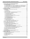
7.2. SETUP MORE VARS: Internal Variables (VARS)............................................................................ 125
7.3. SETUP MORE DIAG: Using the Diagnostics Functions.................................................................. 127
7.3.1. Accessing the Diagnostic Features .................................................................................................... 128
7.4. Using the M300E/EM Analyzer’s Analog Outputs. .................................................................................... 129
7.4.1. Accessing the Analog Output Signal Configuration Submenu ........................................................... 129
7.4.2. Analog Output Voltage / Current Range Selection ............................................................................. 131
7.4.3. Calibration of the Analog Outputs....................................................................................................... 133
7.4.3.1. Enabling or Disabling the AutoCal for an Individual Analog Output............................................ 133
7.4.3.2. Automatic Calibration of the Analog Outputs .............................................................................. 134
7.4.3.3. Individual Calibration of the Analog Outputs ............................................................................... 136
7.4.3.4. Manual Calibration of the Analog Outputs Configured for Voltage Ranges................................ 137
7.4.3.5. Manual Adjustment of Current Loop Output Span and Offset .................................................... 139
7.4.4. Turning an analog output Over-Range Feature ON/OFF................................................................... 142
7.4.5. Adding a Recorder Offset to an analog output ................................................................................... 143
7.4.6. Selecting a Test Channel Function for Output A4 .............................................................................. 144
7.4.7. AIN Calibration.................................................................................................................................... 146
7.5. SETUP MORE ALRM: Using the Gas Concentration Alarms ........................................................... 147
7.5.1. Setting the M300E Concentration Alarm Limits.................................................................................. 147
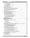
8. REMOTE OPERATION .................................................................................................... 149
8.1. SETUP MORE COMM: Using the Analyser’s Communication Ports ................................................ 149
8.1.1. RS-232 DTE and DCE Communication.............................................................................................. 149
8.1.2. COMM Port Default Settings............................................................................................................... 149
8.1.3. COMM Port Baud Rate....................................................................................................................... 151
8.1.4. COMM Port Communication Modes ................................................................................................... 152
8.1.5. COMM Port Testing ............................................................................................................................ 154
8.1.6. Machine ID.......................................................................................................................................... 155
04288D DCN5752


