


Optional Hardware and Software Teledyne API – Technical Manual - Model 300E Family CO Analyzers
64
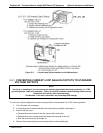
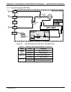
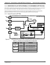
5. Disconnect the current loop option PCA from the appropriate connector on the motherboard (see Figure
5-2).
6. Each connector, J19 and J23, requires two shunts. Place one shunt on the two left most pins and the
second shunt on the two pins next to it (see Figure 5-2).
6 spa
re shunts (P/N CN0000132) were shipped with the instrument attached to JP1 on the back of
the instruments keyboard and display PCA.
7. Reattach the top case to the analyzer.
8. The analyzer is now ready to have a voltage-sensing, recording device attached to that output.
9. Calibrate the analog output as described in Section 7.4.3.
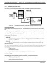
5.5. EXPENDABLES AND SPARES KITS (OPTIONS 42A, 45)
Expendables Kit, Option 42A: one-year supply of replacement particulate filters (47mm diameter)
Spares Kit, Option 45: spare parts for one unit
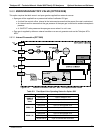
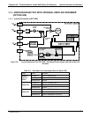
5.6. CALIBRATION VALVES (OPTIONS 50A, 50B, 50E, 50H)
The M300E/EM Gas Filter Correlation Carbon Monoxide Analyzer has a variety of available options involving
various valves for controlling the flow of calibration gases. From an operational and software standpoint, all of
the options are the same, only the source of the span and zero gases are different.
5.6.1. GENERAL INFORMATION RELATED TO ALL VALVE OPTIONS
5.6.1.1. Gas Flow Rate
The minimum span gas flow rate required is 800 cm
3
/min; however, the US EPA recommends that there
be an excess of flow at least 800 cm
3
/min of calibration gas.
Zero air will be supplied at ambient pressure from the local atmosphere.
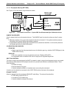
5.6.1.2. Valve Control
The state of the various valves included in these options can be controlled as follows:
Manually from the analyzer’s front panel by using the SIGNAL I/O controls located under the DIAG Menu
(see Section 7.3),
By activating the instru
ment’s AutoCal feature (see Section 9.4),
Remotely by usin
g the external digital control inputs (see Section 9.3.3.3), or
Remotely through the
RS-232/485/Ethernet serial I/O ports (see Appendix A-6 for the appropriate
commands).
5.6.2. ZERO/SPAN VALVE (OPTION 50A)
This valve option is intended for applications where:
Zero air is supplied by a zero air generator like the Teledyne API’s M701 and;
Span gas is supplied by Gas Dilution Calibrator like the Teledyne API’s M700E or M702.
Internal zero/span and sample/cal valves control the flow of gas through the instrument, but because the
generator and calibrator limit the flow of zero air and span gas, no shutoff valves are required.
04288D DCN5752