


Teledyne API – Technical Manual - Model 300E Family CO Analyzers Troubleshooting & Repair
275
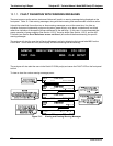
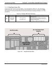
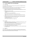
13.1.4.2. Sync Demodulator Status LED’s
Two LED’s located on the Sync/Demod Board and are there to make it obvious that the GFC Wheel is spinning
and the synchronization signals are present:
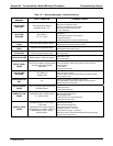
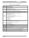
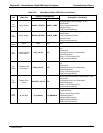
Table 13-3: Sync/Demod Board Status Failure Indications
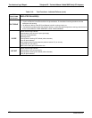
LED FUNCTION FAULT STATUS INDICATED FAILURE(S)
D1
M/R Sensor Status
(Flashes slowly)
LED is stuck
ON or OFF
GFC Wheel is not turning
M/R Sensor on Opto-Pickup Board failed
Sync/Demod Board failed
JP 4 Connector/Wiring faulty
Failed/Faulty +5 VDC Power Supply (PS1)
D2
Segment Sensor
Status
(Flashes quickly)
LED is stuck
ON or OFF
GFC Wheel is not turning
Segment Sensor on Opto-Pickup Board failed
Sync/Demod Board failed
JP 4 Connector/Wiring faulty
Failed/Faulty +5 VDC Power Supply (PS1)
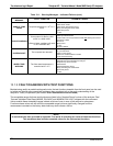
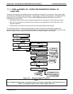
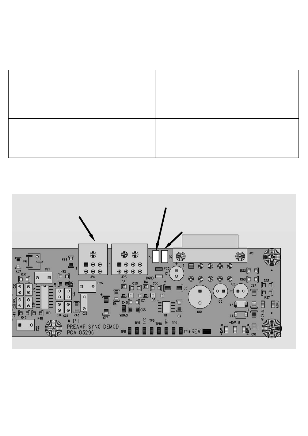
D1 – M/R Sensor Status
D2 – Segment Sensor Status
JP4 Connector to Opto-Pickup
Board
Figure 13-4: Sync/Demod Board Status LED Locations
04288D DCN5752