


Teledyne API – Technical Manual - Model 300E Family CO Analyzers Theory of Operation
237
11.5. ELECTRONIC OPERATION
11.5.1. OVERVIEW
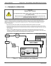
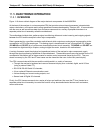
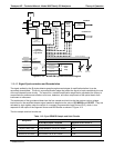
Figure 11-9 shows a block diagram of the major electronic components of the M300E/EM.
At the heart of the analyzer is a microcomputer/CPU that controls various internal processes, interprets data,
makes calculations, and reports results using specialized firmware developed by Teledyne API. It communicates
with the user as well as receives data from and issues commands to a variety of peripheral devices via a
separate printed circuit assembly called the motherboard.
The motherboard collects data, performs signal conditioning duties and routes incoming and outgoing signals
between the CPU and the analyzer’s other major components.
Data is generated by a gas-filter-correlation optical bench which outputs an analog signal corresponding to the
concentration of CO in the sample gas. This analog signal is transformed into two, pre-amplified, DC voltages
(CO MEAS and CO REF) by a synchronous demodulator printed circuit assembly. CO MEAS and CO REF are
converted into digital data by a unipolar, analog-to-digital converter, located on the motherboard.
A variety of sensors report the physical and operational status of the analyzer’s major components, again
through the signal processing capabilities of the motherboard. These status reports are used as data for the CO
concentration calculation and as trigger events for certain control commands issued by the CPU. They are
stored in memory by the CPU and in most cases can be viewed but the user via the front panel display.
The CPU communicates with the user and the outside world in a variety of manners:
Through the analyzer’s keyboard and vacuum florescent display over a clocked, digital, serial I/O bus
(using a protocol called I
2
C);
RS-232 & RS-485 Serial I/O channels;
Via an optional Ethernet communications card:
Various analog and current analog outputs, and
Several sets of Digital I/O channels.
Finally, the CPU issues commands via a series of relays and switches (also over the I
2
C bus) located on a
separate printed circuit assembly to control the function of key electromechanical devices such as heaters,
motors and valves.
04288D DCN5752