


Teledyne API – Technical Manual - Model 300E Family CO Analyzers Getting Started
51
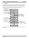
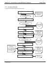
3.6. INITIAL CALIBRATION OF THE M300E/EM
To perform the following calibration you must have sources for zero air and span gas available for input into the
sample port on the back of the analyzer. See Section 3.4 for instructions for connecting these gas sources.
The initial calibration
should be carried out using the same reporting range set up as used during the analyzer’s
factory calibration. This will allow you to compare your calibration results to the factory calibration as listed on
the Final Test and Validation Data Sheet.
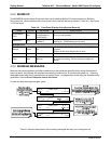
If both available iDAS parameters for a specific gas type are being reported via the instruments analog outputs
e.g. CONC1 and CONC2 when the DUAL range mode is activated, separate calibrations should be carried out
for each parameter.
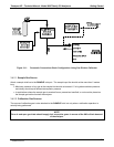
Use the LOW button when calibrating for CONC1 (equivalent to RANGE1).
Use the HIGH button when calibrating for CONC2 (equivalent to RANGE2).
See Manual Addendum, P/N 06270 for more information on the configurable analog output reporting ranges.
NOTE
The following procedure assumes that the instrument does not have any of the available Valve Options
installed.
See Section 9.3 for instructions for calibrating instruments possessing valve options.
3.6.1. INTERFERENTS FOR CO
2
MEASUREMENTS
It should be noted that the gas filter correlation method for detecting CO is subject to interference from a number
of other gases that absorb IR in a similar fashion to CO. Most notable of these are water vapor, CO
2
, N
2
O
(nitrous oxide) and CH
4
(methane). The M300E/EM has been successfully tested for its ability to reject
interference from of these sources, however high concentrations of these gases can interfere with the
instrument’s ability to make low-level CO measurements.
For a more detailed discussion of this topic, see Section 11.2.1.3.
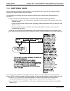
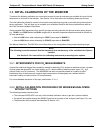
3.6.2. INITIAL CALIBRATION PROCEDURE FOR M300E/EM ANALYZERS
WITHOUT OPTIONS
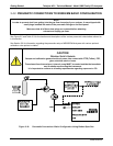
The following procedure assumes that:
The instrument DOES NOT have any of the available calibration valve or gas inlet options installed;
Cal gas will be supplied through the SAMPLE gas inlet on the back of the analyzer (see Figure 3-2), and;
The pne
umatic setup matches that described in Section 3.4.2.
04288D DCN5752