


Troubleshooting & Repair Teledyne API – Technical Manual - Model 300E Family CO Analyzers
274
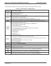
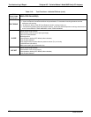
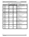
See Appendix A-4 for a complete list of the parameters available for review under this menu
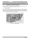
13.1.4. INTERNAL ELECTRONIC STATUS LED’S
Several LED’s are located inside the instrument to assist in determining if the analyzer’s CPU, I
2
C bus and relay
board, GFC Wheel and the sync/demodulator board are functioning properly.
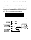
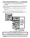
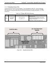
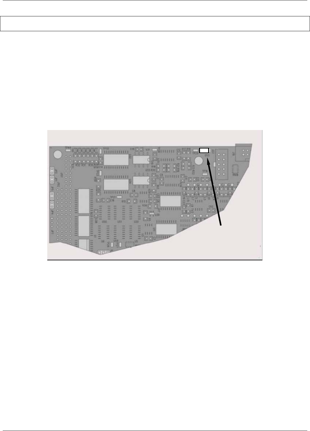
13.1.4.1. CPU Status Indicator
DS5, a red LED, that is located on upper portion of the motherboard, just to the right of the CPU board, flashes
when the CPU is running the main program loop. After power-up, approximately 30 to 60 seconds, DS5 should
flash on and off. If characters are written to the front panel display but DS5 does not flash then the program files
have become corrupted. If after 30 – 60 seconds neither the DS5 is flashing or no characters have been written
to the front panel display then the CPU is bad and must be replaced.
Motherboard
P/N 04069
CPU Status LED
Figure 13-3: CPU Status Indicator
04288D DCN5752