


4 - 5
4 AUXILIARY AND APPLIED FUNCTIONS
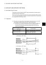
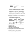
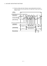
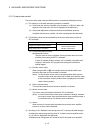
(2) Watch data
(a) This data is used to perform the limit switch output function. This data is
comparison data to output the ON/OFF signal. The output device is
ON/OFF-controlled according to the ON region setting.
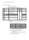
(b) As the watch data, motion control data or optional word device data can be
used.
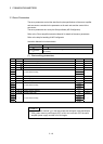
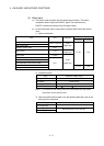
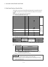
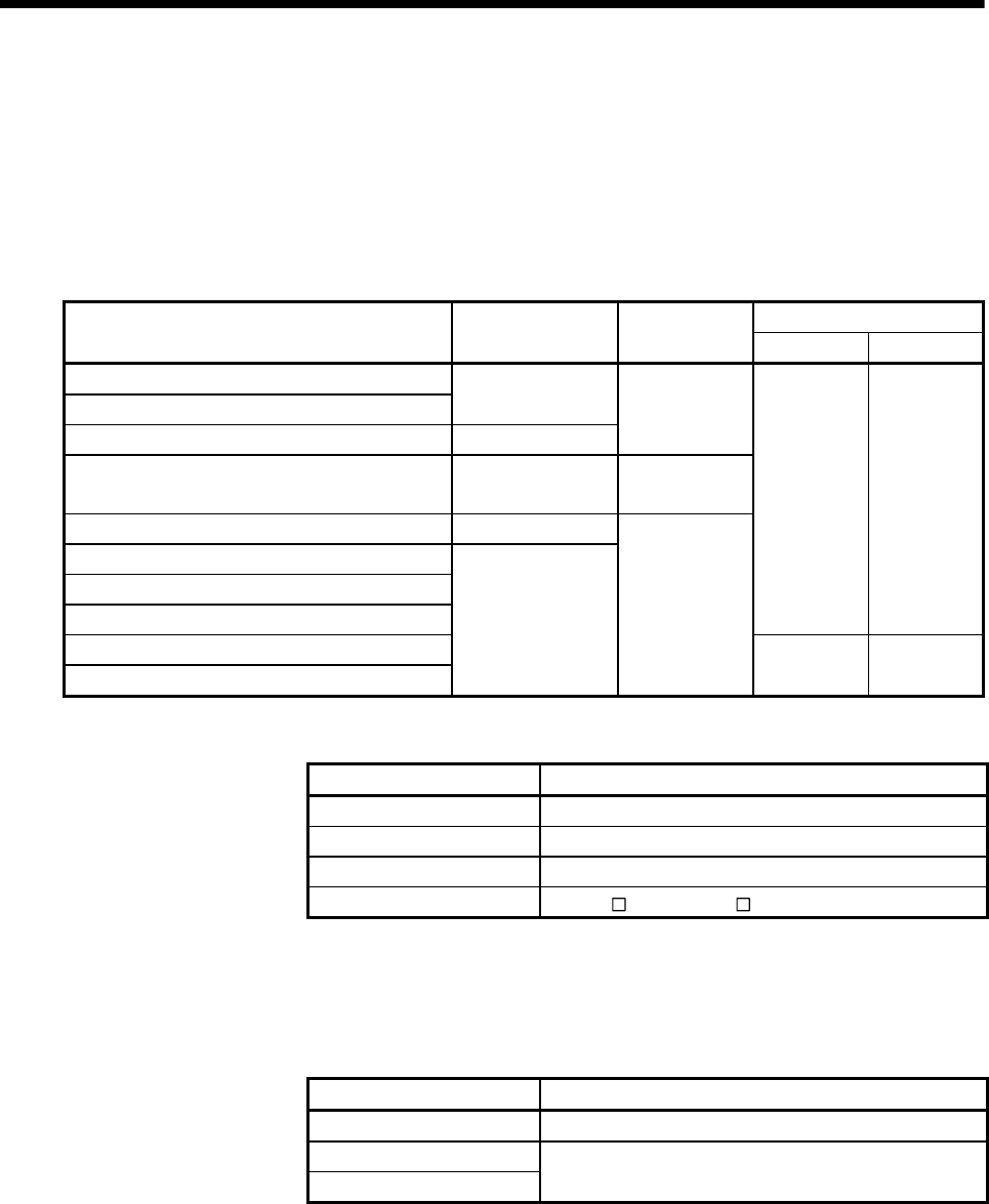
1) Motion control data
Axis No. setting range
Item Unit Data type
Q173DCPU Q172DCPU
Feed current value
Real current value
Position command
Deviation counter value PLS
32-bit
integer type
Motor current 0.1%
16-bit
integer type
Motor speed 0.1r/min
Cam shaft within-one-revolution current value
Feed current value (Virtual)
After-differential current value (Virtual)
1 to 32 1 to 8
After-differential encoder current value
Encoder current value
PLS
32-bit
integer type
1 to 12 1 to 8
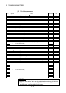
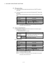
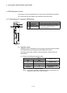
2) Word device data
Item Device No. setting range
Data register D0 to D8191
Link register W0 to W1FFF
Motion register #0 to #7999
Multiple CPU area device
U
\G10000 to U \G (10000+p-1)
(Note-1)
(Note-1) : "p" indicates the user setting area points of the Multiple CPU high speed
transmission area for the each CPU.
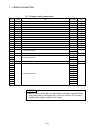
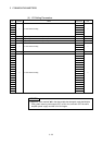
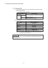
3) When the optional device data is set, the following data type is set as the
data type to be compared.
Data type Remarks
16-bit integer type
32-bit integer type
64-bit floating-point type
Set the device No. as an even No..