


2 - 11
2 MULTIPLE CPU SYSTEM
2.3 Communication between the PLC CPU and the Motion CPU in the Multiple CPU System
2.3.1 CPU shared Memory
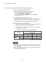
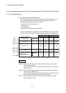
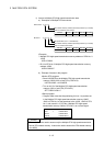
(1) Structure of CPU shared memory
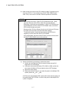
The CPU shared memory is memory provided for each CPU module by which
data is written or read between CPU modules of a Multiple CPU system.
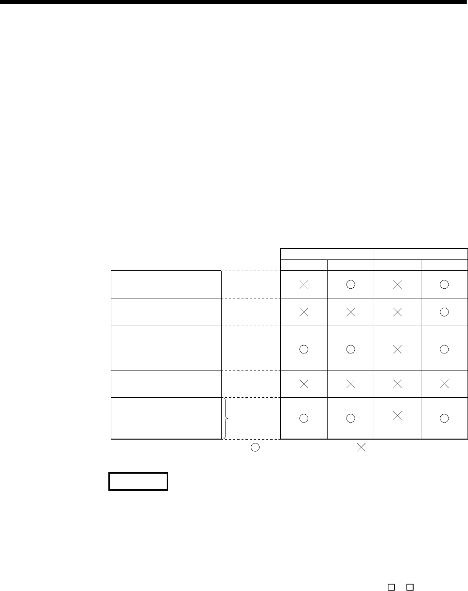
The CPU shared memory consists of four areas.
• Self CPU operation information area
• System area
• User setting area
• Multiple CPU high speed transmission area
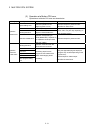
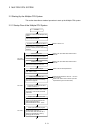
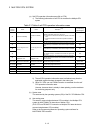
The CPU shared memory configuration and the availability of the communication
from the self CPU using the CPU shared memory by program are shown below.
Multiple CPU
high speed
bus
(Note-2)
0
511
2047
512
2048
4095
4096
9999
10000
up to
24335
(0H)
(1FFH)
(7FFH)
(200H)
(800H)
(FFFH)
(1000H)
(270FH)
(2710H)
(5F0FH)
Self CPU operation
information area
System area
CPU shared memory
User setting area
to
to
to
to
to
to
to
to
to
to
Multiple CPU high speed
transmission area
(Variable size in 0 to
14k[points]: 1k words in unit)
Write Read Write Read
(Note-2) (Note-2)
(Note-2) (Note-2)
(Note-1)
(Note-3) (Note-3)(Note-3)
Unusable
Self CPU Other CPU
: Communication allowed
: Communication not allowed
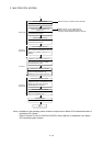
REMARK
(Note-1) : Use the MULTW instruction to write to the user setting area of the self
CPU in the Motion CPU.
Use the S. TO instruction to write to the user setting area of the self CPU
in the PLC CPU.
(Note-2) : Use the MULTR instruction to read the shared memory of self CPU and
other CPU in the Motion CPU.
Use the FROM instruction/Multiple CPU area device (U
\G ) to read the
shared memory of the Motion CPU from the PLC CPU.
(Note-3) : Refer to Section 2.3.2(1) for the access method of Multiple CPU high
speed transmission area.