


2 - 2
2 MULTIPLE CPU SYSTEM
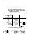
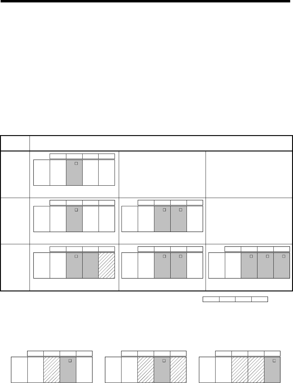
2.1.2 Installation position of CPU module
Up to four PLC CPUs and Motion CPUs can be installed from the CPU slot (the right
side slot of the power supply module) to slots 2 of the main base unit.
The Motion CPU module cannot be installed in the CPU slot.
The PLC CPU module must be installed in the CPU slot (CPU No.1) in the Multiple
CPU system.
There is no restriction on the installation order for CPU modules (CPU No.2 to 4).
(Note): Refer to the manual for each CPU module when the High performance PLC
CPU module, Process CPU module, PC CPU module and C controller module
is mounted in the combination of Multiple CPU.
Table 2.1 Example for CPU module installation
Number of
CPUs
Installation position of CPU module
2
QnUD(H)
CPU
CPU 0 1 2
Power
supply
Q17 D
CPU
CPU
No.2
CPU
No.1
CPU
No.3
CPU
No.4
—— ——
3
QnUD(H)
CPU
CPU 0 1 2
Power
supply
Q17 D
CPU
CPU
No.2
CPU
No.1
CPU
No.3
CPU
No.4
QnUD(H)
CPU
QnUD(H)
CPU
CPU 0 1 2
Power
supply
Q17 D
CPU
CPU
No.2
CPU
No.1
CPU
No.3
CPU
No.4
Q17 D
CPU
——
4
QnUD(H)
CPU
CPU 0 1 2
Power
supply
Q17 D
CPU
CPU
No.2
CPU
No.1
CPU
No.3
CPU
No.4
QnUD(H)
CPU
CPU
empty
Q17 D
CPU
QnUD(H)
CPU
CPU 0 1 2
Power
supply
Q17 D
CPU
CPU
No.2
CPU
No.1
CPU
No.3
CPU
No.4
QnUD(H)
CPU
Q17 D
CPU
Q17 D
CPU
QnUD(H)
CPU
CPU 0 1 2
Power
supply
Q17 D
CPU
CPU
No.2
CPU
No.1
CPU
No.3
CPU
No.4
CPU012: Slot numbe
r
An empty slot can be reserved for future addition of a CPU module.
Set the number of CPU modules including empty slots in the Multiple CPU setting, and
set the type of the slots to be emptied to "PLC (Empty)" in the CPU setting.
Q17 D
CPU
Q17 D
CPU
QnUD(H)
CPU
CPU 0 1 2
Power
supply
CPU
No.2
CPU
No.1
CPU
No.3
CPU
No.4
(Example 2)
Q17 D
CPU
QnUD(H)
CPU
CPU 0 1 2
Power
supply
CPU
No.2
CPU
No.1
CPU
No.3
CPU
No.4
(Example 1)
QnUD(H)
CPU
CPU 0 1 2
Power
supply
CPU
No.2
CPU
No.1
CPU
No.3
CPU
No.4
(Example 3)
CPU
empty
CPU
empty
CPU
empty
CPU
empty
CPU
empty