


2 - 12
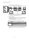
2 MULTIPLE CPU SYSTEM
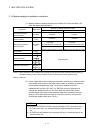
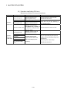
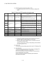
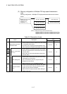
(a) Self CPU operation information area (0H to 1FFH)
1) The following information of self CPU is stored as the Multiple CPU
system
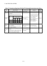
Table 2.3 Table of self CPU operation information areas
CPU shared
memory
address
Name Detail
Description
(Note)
Corresponding
special register
0H Information availability
Information availability
flag
The area to confirm if information is stored in the self CPU's
operation information area (1H to 1FH) or not.
• 0: Information not stored in the self CPU's operation information
area.
• 1: Information stored in the self CPU's operation information
area.
—
1H Diagnostic error Diagnostic error number
An error No. identified during diagnosis is stored in BIN.
SD0
2H
The year and month that the error number was stored in the CPU
shared memory's 1H address is stored with two digits of the BCD
code.
SD1
3H
The date and time that the error number was stored in the CPU
shared memory's 1H address is stored with two digits of the BCD
code.
SD2
4H
Time the diagnostic error
occurred
Time the diagnostic error
occurred
The minutes and seconds that the error number was stored in the
CPU shared memory's 1H address is stored with two digits of the
BCD code.
SD3
5H
Error information
identification code
Error information
identification code
Stores an identification code to determine what error information
has been stored in the common error information and individual
error information.
SD4
6H to 10H Common error information Common error information
The common information corresponding to the error number
identified during diagnosis is stored.
SD5 to SD15
11H to 1BH
Individual error
information
Individual error
information
The individual information corresponding to the error number
identified during diagnostic is stored.
SD16 to SD26
1CH Empty —
Cannot be used
—
1DH Switch status CPU switch status
Stores the CPU module switch status.
SD200
1EH Empty —
Cannot be used
—
1FH CPU operation status CPU operation status
Stores the CPU module's operation status.
SD203
(Note) : Refer to the corresponding special register for details.
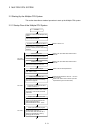
2) The self CPU operation information area is refreshed every time the
applicable register has been changed in the main cycle.
3) Other PLC CPU can use FROM instruction to read data from the self
CPU operation information area.
However, because there is a delay in data updating, use the read data
for monitoring purposes only.
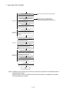
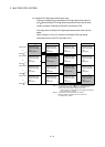
(b) System area
The area used by the operating systems (OS) of the PLC CPU/Motion CPU.
(c) User setting area
The area for communication between CPU modules in the Multiple CPU
system by MULTR/MULTW instruction of Motion CPU.
(PLC CPU use FROM/S.TO instruction or Multiple CPU area devices to
communicate between CPU modules.)
Refer to the Programming Manual of operating system software for
MULTR/MULTW instruction.