


2 - 17
2 MULTIPLE CPU SYSTEM
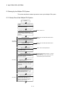
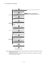
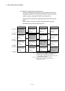
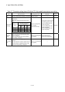
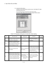
(3) Memory configuration of Multiple CPU high speed transmission
area
Memory configuration of Multiple CPU high speed transmission area is shown
below.
User setting area
Multiple CPU high speed
transmission area
[Variable in 0 to
14k[points]
(Note-1)
]
Automatic refresh area
7)
6)
CPU No.1 send area
3)
2)
4)
5)
1)
(Note-1): Multiple CPU high speed transmission area;
14k[points]: Maximum value when constituted with two CPUs
13k[points]: Maximum value when constituted with three CPUs
12k[points]: Maximum value when constituted with four CPUs
CPU No.2 send area
CPU No.3 send area
CPU No.4 send area
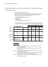
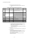
Table 2.5 Description of area
Size
No. Name Description
Setting range Setting unit
1)
Multiple CPU high speed
transmission area
• Area for data transmission between each CPU module
in the Multiple CPU system.
• The area up to 14k [points] is divided between each
CPU module that constitutes the Multiple CPU system.
0 to 14k 1k
2)
3)
4)
5)
CPU No. n send area
(n=1 to 4)
• Area to store the send data of the each CPU module.
• Sends the data stored in the send area of self CPU to
the other CPUs.
• Other CPU send area stores the data received from
the other CPUs.
0 to 14k 1k
6) User setting area
• Area for data communication with other CPUs using
the Multiple CPU area device.
• Can be accessed by the user program using the
Multiple CPU area device.
• Refer to Section 2.3.2 (1) for details of this area.
0 to 14k 2
7)
Automatic refresh
area
• Area for communicating device data with other CPUs
by the communication using the automatic refresh.
• Access by user program is disabled.
• Refer to Section "(4)(b) Automatic refresh setting" for
details of this area.
0 to 14k 2