


2 - 15
2 MULTIPLE CPU SYSTEM
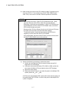
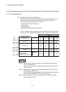
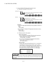
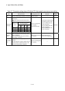
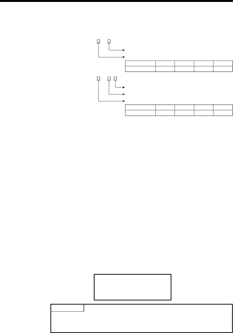
1) Access to Multiple CPU high speed transmission area
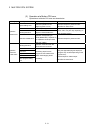
a) Description of Multiple CPU area device
: U \ G
CPU shared memory address (decimal) (10000 to up to 24335)
CPU shared memory address (decimal) (10000 to up to 24335)
First I/O number of CPU module
Bit specification (0 to F : Hexadecimal)
: U \ G .
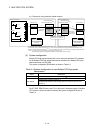
Bit device
CPU No.
First I/O number
3E0(H)
CPU No.1
3E1(H)
CPU No.2
3E2(H)
CPU No.3
3E3(H)
CPU No.4
First I/O number CPU module
CPU No.
First I/O number
3E0(H)
CPU No.1
3E1(H)
CPU No.2
3E2(H)
CPU No.3
3E3(H)
CPU No.4
Word device
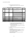
(Example)
• Multiple CPU high speed transmission memory address of CPU No. 2:
10002
U3E1\G10002
• Bit 14 of CPU No. 3 Multiple CPU high speed transmission memory
address 10200
U3E2\G10200.E
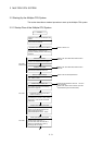
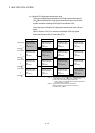
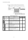
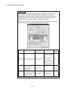
b) Example of access in the program
<Motion SFC program>
• Store K12345678 to the Multiple CPU high speed transmission
memory 10200,10201 of self CPU (CPU No.2).
U3E1\G10200L = K12345678
• Turn on bit 12 of the Multiple CPU high speed transmission
memory 10301 of self CPU (CPU No.3)
SET U3E2\G10301.C
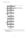
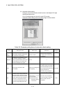
<Servo program>
• Program which executes the positioning for Axis 1 to position set
in the Multiple CPU high speed transmission memory 10400,
10401 of CPU No.1 at the speed set in the 10402, 10403 of CPU
No.1, and uses bit 1 of CPU No.1 Multiple CPU high speed
transmission memory 10404 of CPU No.1 as a cancel signal.
ABS-1
Axis 1, U3E0\G10400
Speed U3E0\G10402
Cancel U3E0\G10404.1
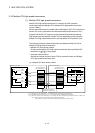
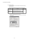
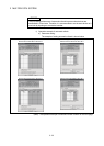
POINT
This method can be used to access only the Multiple CPU high speed transmission
area of CPU shared memory. It cannot be used to access the CPU shared memory
(0 to 4095).