


APP - 9
A
PPENDICES
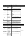
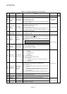
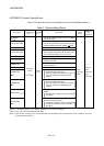
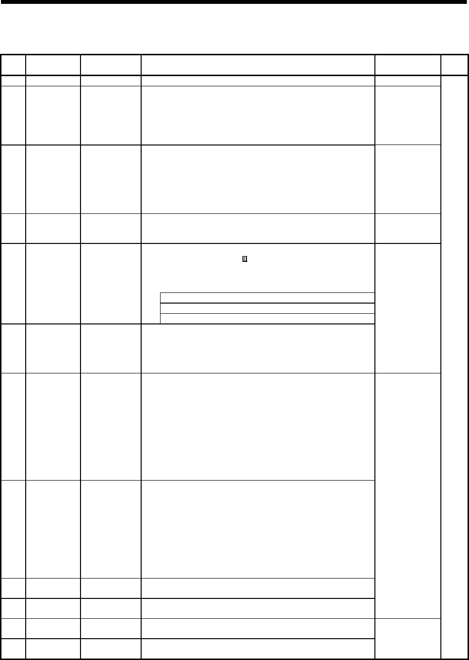
Table 1.2 Special register list (Continued)
No. Name Meaning Details
Set by
(When set)
Remark
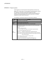
SD395 Multiple CPU No. Multiple CPU No. • CPU No. of the self CPU is stored. S (Initial processing)
SD500
SD501
Real mode axis
information
register
Real mode axis
information register
• The information (Real mode axis: 0/Except real mode axis: 1) used as a real
mode axis at the time of switching from real mode to virtual mode is stored.
SD500 : b0 to b15 (Axis 1 to 16)
SD501 : b0 to b15 (Axis 17 to 32)
• The real mode axis information does not change at the time of switching from
virtual mode to real mode
S (At virtual mode
transition)
SD502
SD503
Servo amplifier
loading
information
Servo amplifier
loading information
• The loading status (loading: 1/non-loading: 0) of the servo amplifier checked
in initial process, and stored as the bit data.
SD502 : b0 to b15 (Axis 1 to 16)
SD503 : b0 to b15 (Axis 17 to 32)
• The axis which turned from non-loading to loading status after power-on is
handled as loaded. (However, the axis which turned from loading to non-
loading status remains as loaded.)
S (Initial processing)
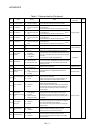
SD504
SD505
SD506
Real mode/virtual
mode switching
error information
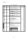
Real mode /virtual
mode switching
error code
• When a mode switching error occurs in real-to-virtual or virtual-to-real
mode switching, or a mode continuation error occurs in the virtual mode, its
error information is stored.
S (Occur an error)
• This signal is used to temporarily suspend SSCNET communication while
servo amplifiers and/or SSCNET
cables after Axis 1 are exchanged with the
power supply ON in a Multiple CPU system.
SD508 stores the command status for "accept waiting" or "execute waiting"
during this process.
0 : Connect/disconnect command accept waiting
-1 : Connect/disconnect execute waiting
SD508
Connect/
Disconnect
(Status)
Connect/
disconnect of
SSCNET
-2 Connect/disconnect executing
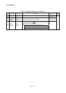
SD510
SD511
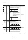
Test mode
request error
It is operating in
requirement error
occurrence of the
test mode, axis
information
• Each axis is stopping: 0/Operating: 1, information is stored as a bit data.
SD510 : b0 to b15 (Axis 1 to Axis 16)
SD511 : b0 to b15 (Axis 17 to Axis 32)
S (Main processing)
SD512
Motion CPU
WDT error cause
Error meaning of
WDT error occurs
• The following error codes are stored in SD512.
1: S/W fault 1
2: Operation cycle over
3: Q bus WDT error
4: WDT error
201 to 215: Q bus H/W fault
250 to 253: Servo amplifier interface H/W fault
300: S/W fault 3
301: 15 CPSTART instructions of 8 or more points were started
simultaneously.
303: S/W fault 4
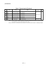
SD513
SD514
SD515
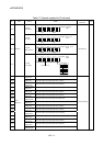
Manual pulse
generator axis
setting error
Manual pulse
generator axis
setting error
information
• Contents of the manual pulse generator axis setting error is stored when the
manual pulse generator axis setting error flag (SM513) turn on.
(Normal: 0/Setting error: 1)
SD513 : The manual pulse generator axis setting error is stored in b0 to b2
(P1 to P3).
The smoothing magnification setting is stored in b3 to b5 (P1 to P3).
SD514 : One pulse input magnification setting error is stored in b0 to b15
(axis 1 to axis 16).
SD515 : One pulse input magnification setting error is stored in b0 to b15
(axis 17 to axis 32).
SD516
Error program
No.
Error program No.
of servo program
• When the servo program setting error flag (SM516) turns on, the erroneous
servo program No. will be stored.
SD517
Error item
information
Error code of servo
program
• When the servo program setting error flag (SM516) turns on, the error code
corresponding to the erroneous setting item will be stored.
S (Occur an error)
SD520 Scan time
Scan time
(1ms units)
• Main cycle is stored in the unit 1ms.
Setting range (0 to 65535[ms])
SD521
Maximum scan
time
Maximum scan
time (1ms units)
• The maximum value of the main cycle is stored in the unit 1ms.
Setting range (0 to 65535[ms])
S (Main processing)