


APP - 7
A
PPENDICES
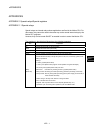
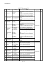
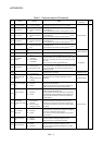
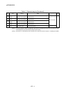
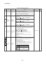
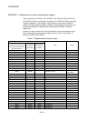
Table 1.2 Special register list (Continued)
No. Name Meaning Details
Set by
(When set)
Remark
SD16
SD17
SD18
SD19
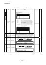
• Individual information corresponding to the diagnostic error (SD0) is stored.
• The error individual information type can be judged by SD4 (individual
information category code).
5: Parameter No.
SD20 No. Meaning
SD21 SD16 Parameter No.
SD22
SD23
SD24
SD17
to
SD26
Empty
SD25 0401H :Base setting
0406H :Motion slot setting
0E00H :Multiple CPU setting (Number of Multiple CPU's)
0E01H :Multiple CPU setting (Operation mode/Multiple CPU
synchronous startup)
E008H :Multiple CPU high speed transmission area setting
(CPU specific send range setting/ (System area))
E009H/E00AH :Multiple CPU high speed transmission area setting
(Automatic refresh setting)
E00BH :Synchronous setting
13: Parameter No./CPU No.
No. Meaning
SD16 Parameter No.
SD17 CPU No.(1 to 4)
SD18
to
SD26
Empty
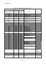
SD26
Error individual
information
Error individual
information
SD53
AC/DC DOWN
counter No.
Number of times
for AC/DC DOWN
• Every time the input voltage fails to or below 85[%] (AC power)/65[%] (DC
power) the rating during calculation of the Motion CPU module, the value is
incremented by 1 and stored in BIN code.
SD60 Fuse blown No.
Module No. with
blown fuse
• The lowest station I/O No. of the module with the blown fuse is stored.
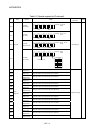
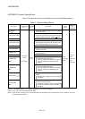
S (Occur an error)
• The CPU switch status is stored in the following format.
B15 B12B11
B8
B7 B4 B3 B0
1)2)
Not used
1) CPU switch status 0: RUN
1: STOP
2) Memory card switch Always OFF
SD200 Status of switch
Status of CPU
switch
• The CPU operating status is stored as indicated in the following figure.
B15 B12B11 B8 B7 B4 B3 B0
1
)
2
)
1) Operating status of CPU 0: RUN
2: STOP
2) STOP cause
(Note) Priority is earliest first
0: RUN/STOP switch
4: Error
SD203
Operating status
of CPU
Operating status
of CPU
S (Main processing)