


4 - 40
4 AUXILIARY AND APPLIED FUNCTIONS
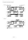
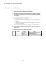
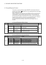
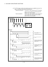
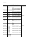
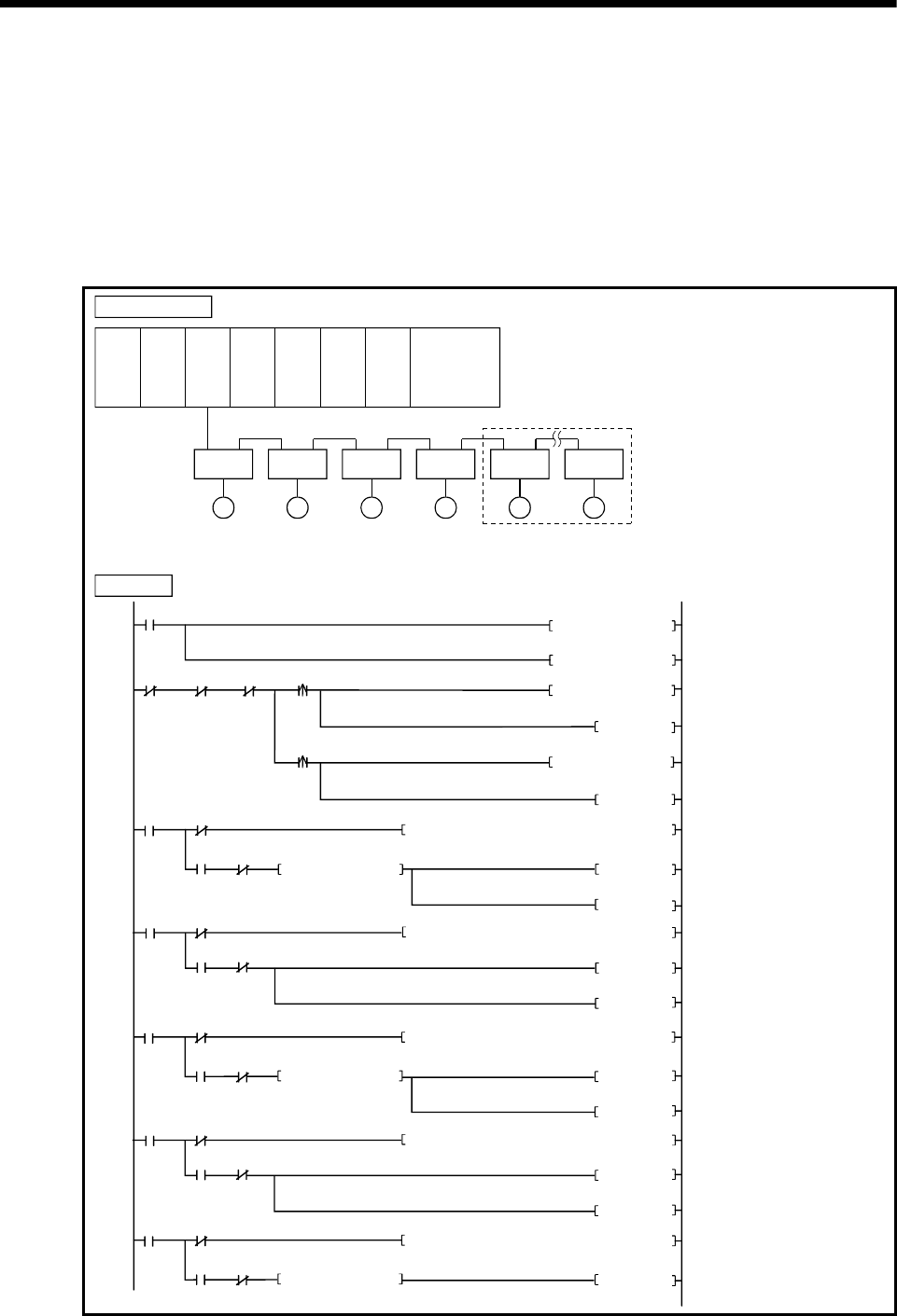
(2) PLC CPU program which connects/disconnects servo amplifiers from Axis 5 on
which is connected to the Motion CPU (CPU No.2).
Disconnect procedure: Turn X0 OFF to ON, and then turn OFF the power
supply of servo amplifier after checking the LED
display "AA" of servo amplifier.
Connect procedure: Turn X1 OFF to ON, and then resume operation of
servo amplifier after checking the servo ready
(M2415+20n) of servo amplifier.
0
SM400
DP.DDRD
H3E1 D100 M10
SD508D50
K-2
D104
MOV
18
K1
D51
MOV
5
M101
M100
M102
X0
K5 D102MOV
M100
SET
K-10 D102MOV
D100
K0=
M10
M11
39
M100
SET
X1
M10
M100
M12
M101
M12
M13
DP.DDWR
H3E1
SD803
M12
D102D50
M100
RST
SET
M101
RST
M102SET
DP.DDRD
H3E1 D100
M10
SD508
D50
57
D100 K-1
=
M10
M11
78
M10
M102
M12
M103
M12
M13
DP.DDWR H3E1
SD803
M12
D104
D50
M102
RST
M103
SET
M103
RST
M104SET
DP.DDRD
H3E1
D100 M10
SD508
D50
96
D100 K0=
M10
M11
M10
M104
M104RST
M101
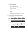
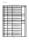
Set "-2" as disconnect execute
command in D104.
Set "-10" as connect command
in D102.
Read the data of SD508 for Multiple
CPU system (CPU No.2) by turning
M102 ON, and store it to data area
(D100) of self CPU.
Write the data of SD803 for Multiple
CPU system (CPU No.2) to D102 by
turning M101 ON.
(Disconnect command/Connect
command)
Read the data of SD508 for Multiple
CPU system (CPU No.2) by turning
M100 ON, and store it to data area
(D100) of self CPU.
Write the data of SD803 for Multiple
CPU system (CPU No.2) to D104 by
turning M103 ON.
(Disconnect execute command)
Read the data of SD508 for Multiple
CPU system (CPU No.2) by turning
M104 ON, and store it to data area
(D100) of self CPU.
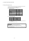
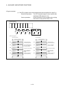
Q61P QnUD(H)
CPU
Q172D
CPU
QY40 QY40 Q172D
LX
QY40
System configuration
Axis 1
AMP
M
Axis 2
AMP
M
Axis 3
AMP
M
Axis 4
AMP
M
Axis 5
AMP
M
Axis 8
AMP
M
Disconnection (From Axis 5 on)
PLC program
Set "5" (Disconnect afrom Axis 5 on)
as disconnect command in D102.