


3 - 19
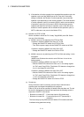
3 COMMON PARAMETERS
3.3 Servo Parameters
The servo parameters control the data fixed by the specifications of the servo amplifier
and servomotor controlled in the parameter set for each axis and the control of the
servomotor.
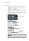
The servo parameters are set by the Setup software (MR Configurator).
Refer to the "Servo amplifier Instruction Manual" for details of the servo parameters.
Refer to the help for handling of MR Configurator.
Instruction Manual list is shown below.
Servo amplifier type Instruction manual name
MR-J3- B MR-J3- B Servo Amplifier Instruction Manual (SH-030051)
MR-J3- B-RJ006
Fully closed loop control MR-J3-
B-RJ006 Servo Amplifier Instruction Manual
(SH-030056)
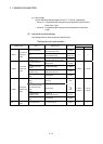
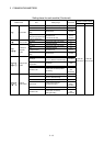
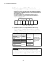
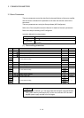
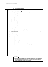
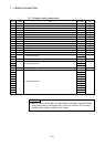
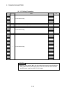
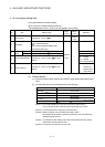
(1) Basic setting parameters
No. Symbol Name Initial value Unit
PA01 — For manufacturer setting 0000h —
PA02 REG Regenerative brake option 0000h —
PA03 ABS Absolute position detection system 0000h —
PA04 AOP1 Function selection A-1 0000h —
PA05 0
PA06 1
PA07
— For manufacturer setting
1
—
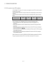
PA08 ATU Auto tuning mode 0001h —
PA09 RSP Auto tuning response 12 —
PA10 INP In-position range 100 PLS
PA11 1000.0
PA12 1000.0
PA13
— For manufacturer setting
0000h
—
PA14 POL Rotation direction selection 0 —
PA15 ENR Encoder output pulse 4000 PLS/rev
PA16 0
PA17 0000h
PA18 0000h
PA19
— For manufacturer setting
000Bh
—
POINTS
(1) When the items marked " " in the above table has changed, make the Multiple
CPU system reset or power supply OFF to ON. And, once turn OFF the servo
amplifier power supply and then turn ON it again.