


3 - 17
3 COMMON PARAMETERS
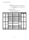
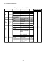
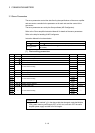
3.2.2 I/O number of each CPU modules
In the Multiple CPU system, I/O numbers are assigned to each CPU module to specify
installed CPU modules.
The I/O number for each CPU module is fixed to the corresponding slot and cannot be
changed.
The I/O number allocated to each CPU module in the Multiple CPU system is shown
below.
CPU module
installation position
CPU slot Slot 0 Slot 1 Slot 2
First I/O number 3E00H 3E10H 3E20H 3E30H
The I/O number of PLC CPU/Motion CPU are used in the following cases.
• When writing data to the CPU shared memory of self CPU using the S. TO
instruction.
• When reading data from the CPU shared memory of other CPU using the FROM
instruction.
• When reading data from the CPU shared memory of other CPU using an intelligent
function module device (U
\G )
• When reading device data directly from the Motion CPU from the PLC CPU using the
"D(P).DDRD" instruction.
• When writing device data directly to the Motion CPU from the PLC CPU using the
"D(P).DDWR" instruction.
Refer to Section 2.3.6 or the "Q173DCPU/Q172DCPU Motion controller (SV13/SV22)
Programming Manual (Motion SFC)" for the Motion dedicated PLC instruction.