


4 - 7
4 AUXILIARY AND APPLIED FUNCTIONS
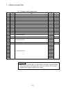
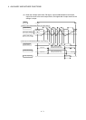
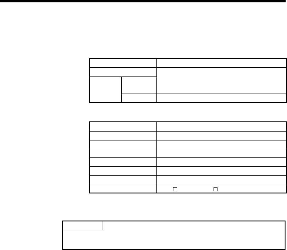
(5) Forced output bit
(a) Set the "forced output bit" when you want to forcibly provide the limit switch
outputs during operation.
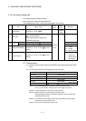
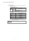
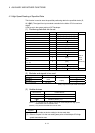
1) The following control is exercised.
Output enable/disable bit Control description
Without setting
OFF
Limit switch outputs are turned ON/OFF on the basis of
the "output enable/disable bit" and ON region setting
(ON Value, OFF Value).
With setting
ON Limit switch outputs are turned ON.
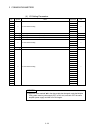
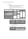
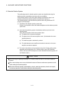
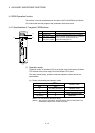
(b) Usable devices
Item Device No. setting range
Input relay X0 to X1FFF
Output relay Y0 to Y1FFF
Internal relay M0 to M8191
Link relay B0 to B1FFF
Annunciator F0 to F2047
Special relay SM0 to SM1999
Multiple CPU area device
U
\G10000.0 to U \G (10000+p-1).F
(Note-1)
(Note-1) : "p" indicates the user setting area points of the Multiple CPU high speed
transmission area for the each CPU.
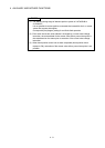
POINT
Refer to Chapter 2 for the user setting area points of the Multiple CPU high speed
transmission area.