


4 - 35
4 AUXILIARY AND APPLIED FUNCTIONS
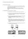
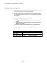
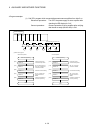
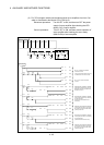
4.10 Optional Data Monitor Function
This function is used to store the data (refer to following table) up to three points per
axis to the specified devices (D, W, #, U
\G) and monitor them.
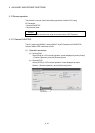
It can be set by the system setting of MT Developer.
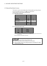
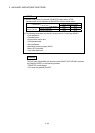
(1) Data that can be set
Data type Unit Number of words
Effective load ratio [%] 1
Regenerative load ratio [%] 1
Peak load ratio [%] 1
Position feed back [PLS] 2
Absolute position encoder within one-
revolution position
[PLS] 2
Load inertia ratio [ 0.1] 1
Position loop gain 1 [rad/s] 1
Bus voltage [V] 1
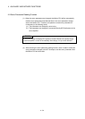
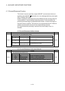
(2) Devices that can be set
Word device Device that can be set
D 0 to 8191
W 0 to 1FFF
# 0 to 7999
U \G
10000 to (10000+p-1)
(Note-1), (Note-2)
(Note-1): "p" indicates the user setting area points of the Multiple CPU high speed transmission area
for the each CPU.
(Note-2): Only device of the self CPU can be used.
POINT
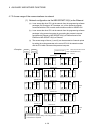
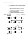
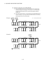
(1) The updating cycle of data is every operation cycle.
(2) Set an even number as device setting in the two word data.
(3) Refer to Chapter 2 for the user setting area points of the Multiple CPU high
speed transmission area.