


3 - 2
3 COMMON PARAMETERS
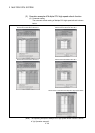
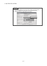
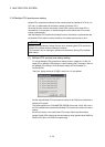
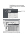
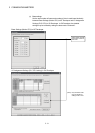
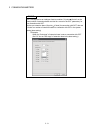
3.1.1 System data settings
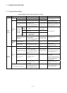
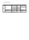
The table below lists the system data items to be set.
Item Setting range Initial value Remark
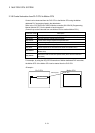
Main base 8/12 slots Main base: 8 slots
Base setting
Extension base None/2/3/5/8/10/12 slots None
Set the number of slots in the main
base or extension base.
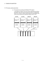
No. of CPU 2/3/4 modules 2 modules
Set the total number of Multiple
CPUs including PLC CPU(s).
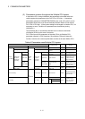
Error operation mode at the
stop of CPU
Stop/do not stop all CPUs upon an
error in CPU No. 1 to 4.
(The setting range varies depending
on the number of Multiple CPUs.)
Stop all CPUs upon error
in CPU Nos. 1 to 4
Set whether or not to stop the entire
system when a CPU stop error
occurs in each CPU.
CPU
specific
send range
0 to 14k points
Varies depending on the
number of CPUs.
System
area
1 to 2k points 1
Multiple CPU
high speed
transmission
area setting
Automatic
refresh
setting
Point : 2 to 14336 points
Start : Set target device for
automatic refresh.
None
Refer to Section 2.3.2.
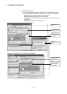
Multiple CPU
setting
Multiple CPU synchronous
startup setting
Set/do not set CPU No. 1 to 4 as the
synchronized startup.
(The setting range varies depending
on the number of Multiple CPUs.)
Set CPU No. 1 to 4 as
the synchronized startup.
Refer to Section 2.3.5.
Module arrangement
Within the main base and extension
base slots
None
Install the modules controlled by the
self CPU in the main base and/or
extension base(s).
Common
system
parameters
Motion slot
setting
Individual module Varies depending on the module.
Varies depending on the
module.
Set detailed items for each module
controlled by the self CPU.
Operation cycle
0.4ms/0.8ms/1.7ms/3.5ms/7.1 ms/
14.2ms/Auto
Auto
Set the operation cycle of motion
control.
Operation at STOP to RUN
M2000 is turned on by switching
from STOP to RUN./M2000 is
turned on by switching from STOP
to RUN and setting 1 in the set
register.
M2000 is turned on by
switching from STOP to
RUN.
Set the condition in which the PLC
ready flag (M2000) turns on.
Forced stop
(Note-1)
None/X(PX) (0 to 1FFF)/
M (0 to 8191)
None
Set the bit device to use forced stop
in the program.
However, the forced stop input by
EMI terminal of Motion CPU module
cannot be invalidated using
parameter setting.
System basic
setting
Latch range
M (0 to 8191)/B (0 to 1FFF)/
F (0 to 2047)/D (0 to 8191)/
W (0 to 1FFF)
None
Set the latch range of device
memory.
Individual
parameters
Self CPU installation position setting
Set self CPU/other CPU/CPU
(empty) for slots 0/1/2. (The setting
range varies depending on the
number of Multiple CPUs installed.)
None
Set the installation position of the
self CPU in the main base.