


4 - 12
4 AUXILIARY AND APPLIED FUNCTIONS
4.4 ROM Operation Function
This function is used to operate based on the data in the FLASH ROM built-in Motion
CPU module that the user programs and parameters have been stored.
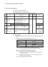
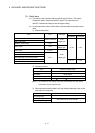
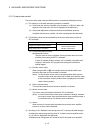
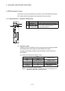
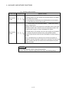
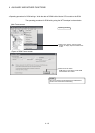
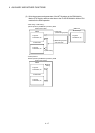
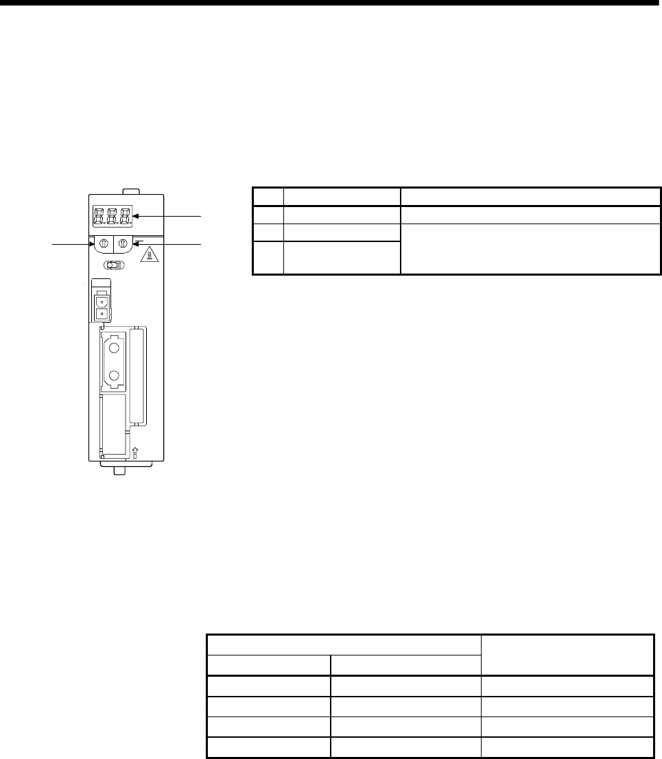
4.4.1 Specifications of 7-segment LED/Switches
No. Items Functions
1) 7-segment LED • Indicate the operation state and error information.
2) Rotary switch 1 (SW1)
3) Rotary switch 2 (SW2)
• Set the operation mode (Normal mode, Installation
mode and mode operated by ROM, etc.)
• Each switch setting is 0 to F.
STOP RUN
0
8
C
4
1
2
3
5
6
7
9
A
B
D
E
F
0
8
C
4
1
2
3
5
6
7
9
A
B
D
E
F
Q172DCPU
CN1
1
CAUTI ON
2
SW
BAT
FRONT
EMI
1)
3)2)
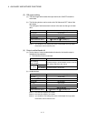
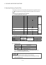
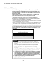
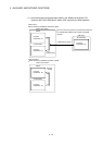
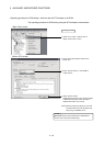
(1) Operation mode
"Operation mode" of the Motion CPU is set by the rotary switch setting of Motion
CPU module at the power supply ON of the Multiple CPU system.
The rotary switch setting, operation mode and operation mode overview are
shown below.
(a) Rotary switch setting and operation mode
Rotary switch setting
(Note-1)
SW1 SW2
Operation mode
A Any setting (Except C) Installation mode
0 0 Mode operated by RAM
0 6 Mode operated by ROM
Any setting C
SRAM clear
(Note-2)
(Note-1) : Do not set except the above setting.
(Note-2) : The programs, parameters, absolute position data, and latch data in the
SRAM built-in Motion CPU module are cleared.