


4 - 11
4 AUXILIARY AND APPLIED FUNCTIONS
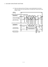
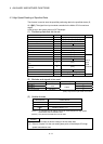
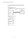
4.3 High-Speed Reading of Specified Data
This function is used to store the specified positioning data in the specified device (D,
W, U
\G). The signal from input module controlled in the Motion CPU is used as a
trigger.
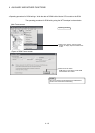
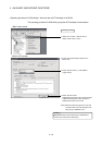
It can be set in the system setting of MT Developer.
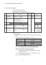
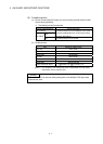
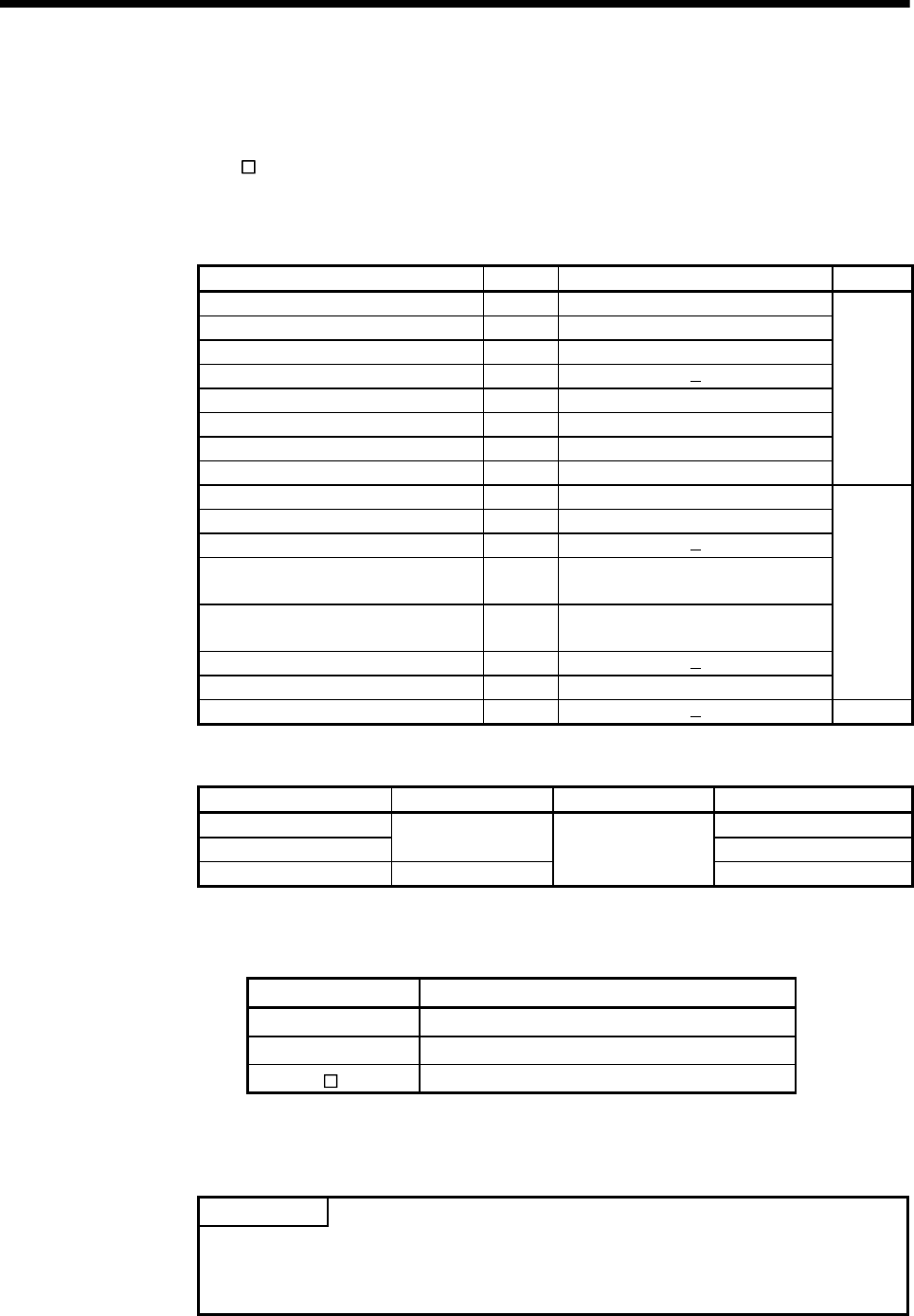
(1) Positioning data that can be set
Setting data Word No. Unit Remarks
Position command (Feed current value) 2
10
-1
[
µ
m], 10
-5
[inch], 10
-5
[degree], [PLS]
Actual current value 2
10
-1
[
µ
m], 10
-5
[inch], 10
-5
[degree], [PLS]
Position droop (Deviation counter value) 2 [PLS]
M-code 1
Torque limit value 1 [%]
Motor current 1 [%]
Motor speed 2 [r/min]
Servo command value 2 [PLS]
Virtual servomotor feed current value 2 [PLS]
Synchronous encoder current value 2 [PLS]
Virtual servo M-code 1
Current value after main shaft differential
gear
2 [PLS]
Current value within one revolution of
cam axis
2 [PLS]
Execute cam No. 1
Execute stroke amount 2
10
-1
[
µ
m], 10
-5
[inch] [PLS]
Valid in
SV22
virtual
mode only
Optional address (Fixed to 4 bytes) 2
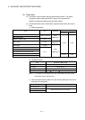
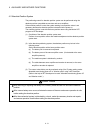
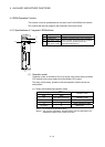
(2) Modules and signals to be used
Input module Signal Read timing Number of settable points
Q172DEX 2
Q173DPX
TREN
3
PLC input module
(Note)
PX device
0.8[ms]
8
(Note) : Only one PLC input module can be used.
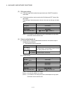
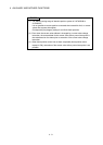
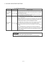
(3) Usable devices
Word devices Usable devices
D 0 to 8191
W 0 to 1FFF
U \G
10000 to (10000 + p-1)
(Note-1), (Note-2)
(Note-1): "p" indicates the user setting area points of the Multiple CPU high speed
transmission area for the each CPU.
(Note-2): Only device of the self CPU can be used.
POINT
(1) Set an even number as device setting in the two word data.
(2) Refer to Chapter 2 for the user setting area points of the Multiple CPU high
speed transmission area.