


2 - 28
2 MULTIPLE CPU SYSTEM
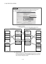
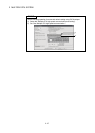
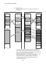
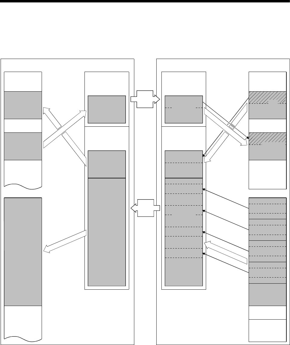
(b) Operation example
The example of operating Multiple CPU high speed refresh function is
shown below.
U3E1\G10000
U3E0\G10000
D640
Motion CPU (CPU No.2)
Control change
register
D0
D639
PLC CPU (CPU No.1)
Internal relay
Multiple CPU high speed
transmission area
Internal relay
Multiple CPU high speed
transmission area
Data register Data register
M3200
M3839
M0
M2399
M2400
M3039
M3040
M3199
M3840
Automatic
refresh area
Automatic
refresh area
CPU No.1
transmitting data
CPU No.2
receiving data
U3E1\G10000
U3E0\G10000
CPU No.1
receiving data
CPU No.2
transmitting data
Automatic
refresh area
Automatic
refresh area
M3200
M3839
M0
M2399
M2400
M3039
M3040
M3199
M3840
D640
D0
D639
M2495
M2496
M3295
M3296
M8191
Axis command
signal
D8191
D704
D703
D80
D60
D40
D20
D19
D79
D59
D39
D2,D3
D12,D13
D62,D63
D72, D73
D42,D43
D52,D53
D22,D23
D32,D33
O
p
e
r
a
t
i
o
n
c
y
c
l
e
O
p
e
r
a
t
i
o
n
c
y
c
l
e
O
p
e
r
a
t
i
o
n
c
y
c
l
e
O
p
e
r
a
t
i
o
n
c
y
c
l
e
M
a
i
n
c
y
c
l
e
M
a
i
n
c
y
c
l
e
M
a
i
n
c
y
c
l
e
O
p
e
r
a
t
i
o
n
c
y
c
l
e
E
N
D
p
r
o
c
e
s
s
i
n
g
E
N
D
p
r
o
c
e
ssi
n
g
E
N
D
p
r
o
c
e
s
s
i
n
g
3 axis monitor
device
4 axis monitor
device
1 axis monitor
device
2 axis monitor
device
5 to 32 axis
monitor
device
Transfer
in 0.88ms
cycle
Transfer
in 0.88ms
cycle
O
p
e
r
a
t
i
o
n
c
y
c
l
e
Axis
status
• Axis 1 to 4 status information (M2400 to M2495) is transferred to the
automatic refresh area one every operation cycle of the Motion CPU.
• Axis 1 to axis 4 command signals are received from the automatic refresh
area one every operation cycle of the Motion CPU.
• Real current values of Axis 1 to axis 4 and M-code is updated by setting
D0 to D639 of the Motion CPU to the automatic refresh area.
• Every 0.88ms, data in the automatic refresh area of all CPUs are
transferred allowing each CPU to update its data upon its next
independent operation cycle.