


APP - 27
A
PPENDICES
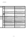
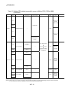
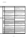
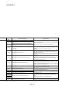
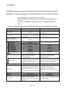
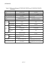
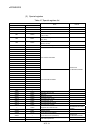
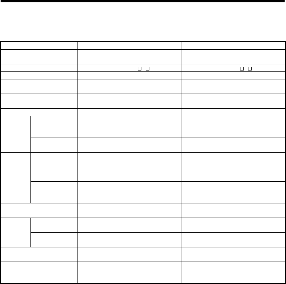
Table 4.1 Differences Between Q173DCPU/Q172DCPU and Q173HCPU/Q172HCPU
(Continued)
Item Q173DCPU/Q172DCPU Q173HCPU/Q172HCPU
Medium of operating system
software
CD-ROM (1 disk) FD (2 disks)
Model of operating system software SW8DNC-SV Q SW6RN-SV Q
CPU module No.1 QnUD(H)CPU Qn(H)CPU
Installation orders CPU No.2 or later No restriction
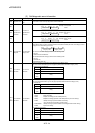
Install Motion CPU module on the right-hand side
of PLC CPU module.
Combination of Motion CPU
modules
Q173DCPU/Q172DCPU only
Combination with
Q173CPUN(-T)/Q172CPUN(-T).
CPU empty slot Settable between CPU modules Not settable between CPU modules
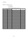
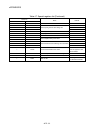
Multiple CPU high
speed transmission
area
Provided None
CPU shared
memory
Access by Multiple
CPU shared memory
Possible Impossible
Memory
Multiple CPU high speed transmission area in
CPU shared memory
Automatic refresh area in CPU shared memory
Automatic refresh
setting
32 range possible 4 range possible
Automatic
refresh
Multiple CPU high
speed refresh
function
Provided None
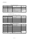
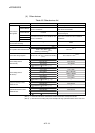
LED display 7-segment LED display
Each LED of MODE, RUN, ERR, M.RUN, BAT
and BOOT
Latch (1)
It is possible to clear with latch clear(1) and latch
clear (1)(2) of remote latch clear.
Range which can be cleared with the latch clear
key.
Latch range
setting
Latch (2)
It is possible to clear with lath clear(1)(2) of
remote latch clear.
Range which cannot be cleared with the latch
clear key.
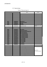
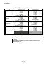
All clear function Execute with installation mode
Turn off the PLC ready flag (M2000) and test
mode ON flag (M9075) to execute all clear.
Release of Multiple CPU related
error
Turn off M2039.
Store the error code to be released in the special
register D9060 and turn off to on the special relay
M9060.