


3 - 16
3 COMMON PARAMETERS
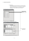
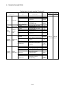
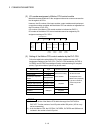
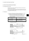
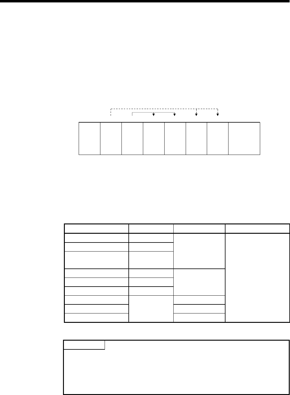
(2) I/O number assignment of Motion CPU control module
Mitsubishi recommends that I/O No. assignment be set as common consecutive
No. throughout all CPUs.
However, the I/O number of the input modules, output modules and input/output
composite modules controlled with the Motion CPU can also be set regardless as
the I/O number of PLC CPU.
(I/O number of the Motion CPU control modules is indicated as PX/PY.)
I/O number of the Motion CPU control modules cannot be assigned by I/O
assignment settings of PLC CPU.
CPU No. 2
control
module
PX0 to PX1F
(X0 to X1F)
Q173D
CPU
Q03UD
CPU
Power supply
module
X40 to X5F
123450
I/O assignment
Y60 to Y7F
CPU No. 1 CPU No. 2 CPU No. 2
control
module
CPU No. 1
control
module
CPU No. 1
control
module
QX41
PY20 to PX3F
(Y20 to Y3F)
QY41 QX41 QY41
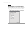
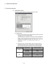
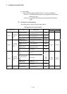
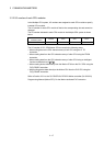
(3) Setting of the Motion CPU control modules by the PLC CPU
Follow the table below when Motion CPU control modules are set in I/O
Assignment Settings of the PLC CPU. (The PLC CPU handles the Q172DLX,
Q172DEX and Q173DPX as intelligent function modules having 32 occupied
points.) Type and number of points may be left unset.
Module name Type Number of points Remarks
Input module Input
Output module Output
Input/Output composite
module
Composite I/O
Selected according
to the module.
Analogue input module Analogue input
Analogue output module Analogue output
Interrupt module (QI60) Interrupt
16 points
Q172DLX 32 points
Q172DEX 32 points
Q173DPX
Intelligent
32 points
• For the control CPU,
set the CPU that
corresponds to the
Motion CPU (required).
• Type and number of
points may be left
unset.
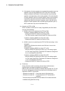
POINT
(1) Set the I/O device of the Motion CPU within the range from PX/PY000 to
PX/PYFFF. Set the number of real I/O points within 256 points. (I/O No. may
not be consecutive.)
(2) As for the Motion CPU, the Q172DLX, Q172DEX, Q173DPX and QI60 are not
included in the number of real I/O points.