


APP - 26
A
PPENDICES
APPENDIX 4 Differences Between Q173DCPU/Q172DCPU and Q173HCPU/Q172HCPU
APPENDIX 4.1 Differences Between Q173DCPU/Q172DCPU and Q173HCPU/Q172HCPU
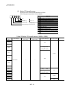
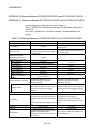
Common differences to each mode are shown in Table 4.1.
Refer to "APPENDIX 4.3 Differences of each mode" for characteristic differences to
each mode.
And, refer to "APPENDIX 4.2 Comparison of devices " for detailed differences of
devices.
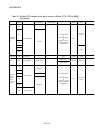
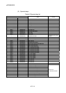
Table 4.1 Differences Between Q173DCPU/Q172DCPU and Q173HCPU/Q172HCPU
Item Q173DCPU/Q172DCPU Q173HCPU/Q172HCPU
Peripheral I/F Via PLC CPU (USB/RS-232) USB/SSCNET
External battery Demand
Add Q6BAT at continuous power failure for 1
month or more.
Forced stop input
• Use EMI terminal of Motion CPU module.
• Use device set by forced stop input setting in
the system setting.
• Use device set by forced stop input setting in
the system setting.
Multiple CPU high speed
transmission memory for data
transfer between CPU modules
Included —
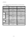
Internal relays (M) 8192 points
Latch relays (L) None (Latch for M is possible by latch setting)
Total 8192 points
Special relays (M) — 256 points
Special relays (SM) 2256 points —
Special registers (D) — 256 points
Special registers (SD) 2256 points —
Motion registers (#) 8736 points 8192 points
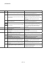
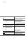
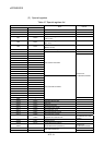
Device
Multiple CPU area devices
(U
\G)
Up to 14336 points —
Motion dedicated PLC instructions
D(P).DDRD, D(P).DDWR, D(P).SFCS,
D(P).SVST, D(P).CHGT, D(P).CHGV,
D(P).CHGA, D(P).GINT
S(P).DDRD, S(P).DDWR, S(P).SFCS,
S(P).SVST, S(P).CHGT, S(P).CHGV,
S(P).CHGA, S(P).GINT
Interlock condition
Multiple instructions are executable continuously
without interlock condition by the self CPU high
speed interrupt accept flag from CPU
.
:CPU No.
Interlock condition by the to self CPU high speed
interrupt accept flag from CPU
is necessary.
Motion modules Q172DLX, Q172DEX, Q173DPX Q172LX, Q172EX, Q173PX
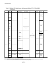
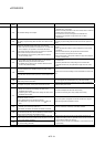
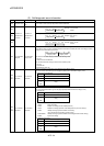
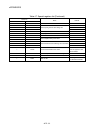
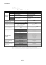
System setting
• QnUD(H)CPU is set as CPU No. 1.
• Only Multiple CPU high speed main base unit
(Q38DB/Q312DB) can be used as main base
unit.
• Motion modules cannot be installed to I/O 0 to 2
slot.
• QnUD(H)CPU is set to CPU No. 1.
• Q3
B can be used as a main base unit.
• Motion modules can be mounted to I/O 0 to 2
slot.
Latch clear Remote operation L.CLR switch
RUN/STOP Remote operation, RUN/STOP switch RUN/STOP switch
ROM operation
• ROM writing is executed with mode operated
by RAM/ mode operated by ROM.
• ROM writing can be executed for the data of
MT Developer.
Rom writing is executed with installation mode/
mode written in ROM.