Honeywell
MK VI MK VIII EGPWS Installation Design Guide
Proprietary notice on title page applies
CAGE CODE: 97896 SCALE: NONE SIZE: A DWG NO: 060-4314-150 REV:
SHEET
99
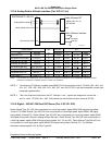
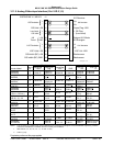
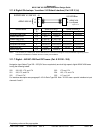
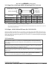
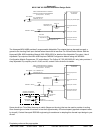
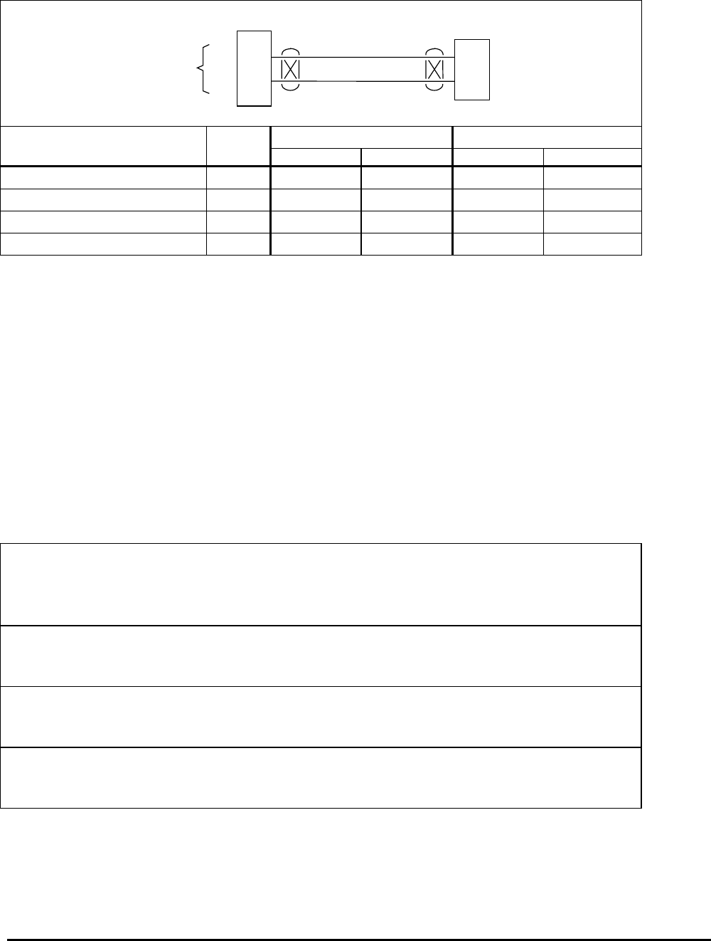
3.12.3 Digital Pitc h & Roll Angle (ARINC 429 High Speed) (Cat. 10 ID 5 & 6)
23
6
J2
AHRS 429 Bus
A
B
EGPWS MK VI / MK VIII
A
B
ARINC 429 AHRS
ARINC 429
High Speed
Digital-AHRS.vsd
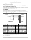
Vendor Model Cat 10 ARINC 429 Bus 1 ARINC 429 Bus 2
IDABA B
Collins AHC-85(D/E only) 6* P1-16 P1-14 P1-24 P1-22
Litef LTR-81 AHRS 6* MP-G7 MP-G8 MP-E5 MP-E6
Litef LCR-92/LCR-93 AHRS 6* J4-08 J4-29 J4-49 J4-07
Honeywell HG1075/1095 IRU 6* J1B-G7 J1B-G8 J1B-E5 J1B-E6
NOTE: The connector pin numbers given in the Table above are to the best knowledge of Honeywell EGPWS engineering. Please
contact the manufacturer’s customer service to confirm your installation.
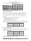
* ID 6 is preferred with Category 2 Air Data with ARINC 429 Barometric Altitude Rate (label 212), otherwise ID 5. ID 6 cannot be
used with analog Air Data interfaces.
3.12.4 Digital – AR INC 429 Dual IOC buses (Cat. 10 ID 253 & 255)
Attitude Input Select Type 253 (IOC bus or equivalent) is a dual high speed, digital ARINC 429 signal having
labels 324, 325, 326, 327, 365 and 361. Attitude Input Select Type 255 (IOC bus or equivalent) is a dual high
speed, digital ARINC 429 signal having labels 324, 325, 333 and 331. For interface description see paragraph
3.4.5 Air Data Type 255.
3.12.5 Instruction s
Using Appendix E Tables 5.2, 5.3.10 and 5.3.10-x as described above, select the Attitude Input
Select type that matches the aircraft configuration, feature preferences, and version (part number)
being installed.
Record the ID number for the Attitude Input Select from Appendix E Table 5.3.10 under the Ident
No. heading for Step (Category) 10 in Appendix E Table 5.2.
Using the Attitude Input Select ID number from Appendix E Table 5.3.10 as “x”, go to Appendix E
Table 5.3.10-x.
The electrical interfaces (pin-outs) for the Attitude Input Select Type are shown in Appendix E
Table 5.3.10-x and are used to generate the installation wiring diagrams.


