Honeywell
MK VI MK VIII EGPWS Installation Design Guide
Proprietary notice on title page applies
CAGE CODE: 97896 SCALE: NONE SIZE: A DWG NO: 060-4314-150 REV:
SHEET 285
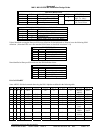
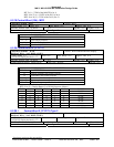
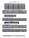
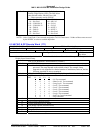
Bits 14 to 16 = Mode, format as follows
Bit 16 Bit 15 Bit 14 MODE
0 0 0 Standby
0 0 1 Weather Only
01 0 Map Only
0 1 1 Windshear Hazard Factor
10 0 Test
1 0 1 Windshear and Turbulence
1 1 0 Weather and Turbulence
1 1 1 Windshear Icon
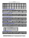
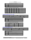
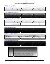
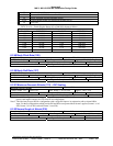
6.2.27 Discrete Word (273) – Bendix Weather Radar Vertical Profile Mode
Discrete Word
Source: EFIS/Weather Radar
LABEL (Octal) 273 Units: N/A Max. Range: N/A Approx. LSB: N/A
Data Bit: 11 + = N/A Sign Bit: N/A Pad Bits: N/A
Transmit Interval (mSec): 100 ms Data Type: Discrete SDI Bits: 9, 10
Some display systems support a vertical profile WXR display where the radar scans up and down. This mode can not
support a terrain display. Therefore when this mode bit is set (indicating that the profile mode is active) the EGPWS is to
treat this as a non-displayable mode.
Mode bit 11 Displayable
Vertical Profile On 1 No
Vertical Profile Off 0 Yes
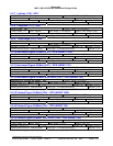
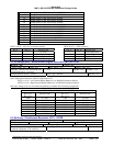
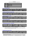
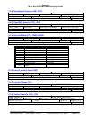
6.2.28 Discrete Word (275) – IC600 only
Discrete Word - (IC600 Packed Discrete Word 4)
Source: IC
LABEL (Octal) 275 Units: N/A Max. Range: N/A Approx. LSB: N/A
Data Bits: Bit 17: See TABLE + = N/A Sign Bit: N/A Pad Bits: N/A
Transmit Interval (mSec): 500 ms Data Type: Discrete SDI Bits: 9, 10
BIT ASSIGNMENTS
Discrete Data Bit Definition
IC outputting MFD format
(its range is displayed)
Bit 17 = 1: IC Driving Display
Bit 17 = 0: IC not Driving Display
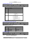
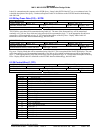
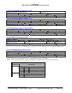
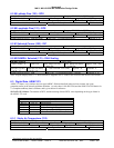
6.2.29 Radio Altitude (164)
RADIO ALTITUDE
Source: ARINC 707 LRRA or IOC
LABEL (Octal) 164 Units: Feet
Max. Range: ± 8,192 Feet
Approx. LSB: 0.125 Foot
Data Bits: 13 to 28 = 16 + = Above Ground Level (AGL) Sign Bit: 29 Pad Bits: 11, 12
Transmit Interval (mSec): 25 to 50 Data Type: 2’s Complement Binary SDI Bits: 9, 10
6.2.30 Glideslope Deviation (174 or 117)
GLIDESLOPE DEVIATION
Source: ARINC 710 ILS or IOC
LABEL (Octal) 174 or 117 Units: See NOTE
Max. Range: ± 0.8 DDM
Approx. LSB: 0.000195 DDM
Data Bits: 17 to 28 = 12 + = Fly Down = Above Beam C/L Sign Bit: 29 Pad Bits: 11 to 16
Transmit Interval (mSec): 33.3 to 66.6 Data Type: 2’s Complement Binary SDI Bits: 9, 10
NOTE: Units = Difference in Depth of Modulation (DDM) 0.0875 DDM = 1 ‘Dot’.


