


Honeywell
MK VI MK VIII EGPWS Installation Design Guide
Proprietary notice on title page applies
CAGE CODE: 97896 SCALE: NONE SIZE: A DWG NO: 060-4314-150 REV:
SHEET 209
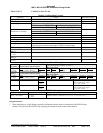
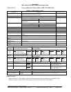
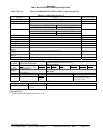
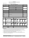
Table 5.3.6.1-10 Honeywell/Bendix EFIS 40/50 (Integrated)
Display Configuration Group 8
Function Value Reference section
Display Type Bendix EFIS 40/50 (Integrated)
Sweep Type Sweep range +/- 90 degrees
Category 7, Options Select Group #1
TA&D Alternate Pop Up: False TA&D Alternate Pop Up: True
Auto Pop Up
2
Pop Up on Caution or Warning. Never Pop Up
5.3.7
Category 7, Options Select Group #1
Peaks Mode
1
Peaks Always Enabled (See Note 1)
5.3.7
Manual select Anytime
Manual deselect Anytime
Auto Range Yes 10 NM
Moving Marker No
Overlay Page No, the display supplies a “TERR” mode annunciation.
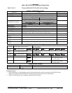
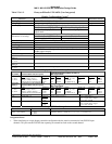
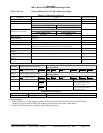
Display bus type ARINC 453
DISPLAY BUS #1
453TX_1
CONNECT TO:
A = J1-58
B = J1-59
Terrain Display data to switching relay/Symbol Generator 4.2.13.2
7.2
DISPLAY BUS #2
453TX_2
CONNECT TO:
A = J1-56
B = J1-57
Terrain Display data to switching relay/Symbol Generator 4.2.13.2
7.2
Display Input Control Group 2
CHANNEL
429_422RX_1
CONNECT TO: WX-IND Bus 1 out
Format: ARINC 429 (Low Speed)
Fault Designation: DISPLAY BUS 1
Bus Type: Basic
A = J2-37
B = J2-36
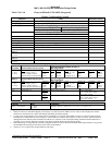
Data
Mode (Display Word 1)
Range (Display Word 2)
Discrete Word (Vertical Profile)
Reference
6.2.26
6.2.20
6.2.27
Label
270
271
273
Sig. Bits
Discrete
Discrete
Discrete
Range
Mode, Tilt, Gain
5-320NM
VP Mode, Bit 11
Signal Type
Basic
Basic
Basic
Resolution
N/A
N/A
N/A
Rate
100 ms
100 ms
100 ms
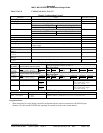
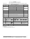
CHANNEL
429RX_3
CONNECT TO: WX-IND Bus 2 out
Format: ARINC 429 (Low Speed)
Fault Designation: DISPLAY BUS 2
Bus Type: Basic
A = J2-41
3
B = J2-40
Data
Mode (Display Word 1)
Range (Display Word 2)
Discrete Word (Vertical Profile)
Reference
6.2.26
6.2.20
6.2.27
Label
270
271
273
Sig. Bits
Discrete
Discrete
Discrete
Range
Mode, Tilt, Gain
5-320NM
VP Mode, Bit 11
Signal Type
Basic
Basic
Basic
Resolution
N/A
N/A
N/A
Rate
100 ms
100 ms
100 ms
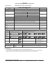
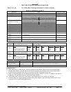
CONN PIN # REFERENCE NAME PIN FUNCTION Polarity/Configuration
J1-32 GND_DISC_12 Reference
4.2.7
6.6.18
Display Select Discrete #1 Type 1 (Momentary)
Gnd = Display Select Toggle
<not> Gnd = Normal
J1-31 GND_DISC_13 Reference
4.2.7
6.6.19
Display Select Discrete #2 Type 1 (Momentary)
Gnd = Display Select Toggle
<not> Gnd = Normal
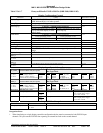
Output 429 Bus Group 0
Channel Pins Comments
429TX_1 (Low Speed) A = J2-43
B = J2-42
Transmits (Section 7) Label sets: 7.1.1.x, 7.1.2.x, 7.1.3.x, and 7.1.4.x
Integration Notes:
1. Peaks Elevations are transmitted digitally to the display via Label 025 on the ARINC 453 bus. They are then displayed as stroked
characters on the bottom left or right of the display (depending on EFIS strapping).
2. To Pop Up the Terrain display for a Terrain Caution or Warning it is necessary for the EFIS to receive two discrete signals from the
EGPWS (one to indicate that the Terrain display is selected and one to indicate that selection was due to an alert). The EFIS needs to
distinguish between manual selection and alert conditions so it will know when it should autorange. Both EFIS and EGPWS start to
autorange on a Caution or Warning to minimize any latency problem displaying status during an alert.
3. When interfacing to a single display controller configuration the bus must be connected to both EGPWS input channels. This prevents
the EGPWS from reporting an external bus fault on the second channel.
4. Software Level 14 required for integrated display and popup.