Honeywell
MK VI MK VIII EGPWS Installation Design Guide
Proprietary notice on title page applies
CAGE CODE: 97896 SCALE: NONE SIZE: A DWG NO: 060-4314-150 REV:
SHEET 166
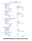
4.2.3.4 Barometric Altitude
Quantity 1
Input Impedance, each leg > 83 K
Ω
Reverse Fault Current
< 200 µA
Input Voltage Range -0.18 VDC to +15 VDC
Input Filter
0.1 Second Low Pass, ± 10%
Input Type Differential
Broken Wire Detect Input will be biased less than -3000 feet
Pin Assignment (Signal Mnemonic):
Signal (+)
Return (-)
J1-62
J1-43
(ALT_H)
(ALT_L)
4.2.3.5 Outside Air Temperature
Quantity 1
Input Impedance, each leg > 100 KΩ
Reverse Fault Current
< 200 µA
Input Voltage Range +0.3 VDC to +0.6 VDC
Input Filter
0.1 Second Low Pass, ± 10%
Input Type Differential
Broken Wire Detect
Input will be biased less than -80° C
Pin Assignment (Signal Mnemonic):
Signal (+)
Return (-)
J1-63
J1-44
(OAT_H)
(OAT_L)
NOTE: For temperature probe voltage reference see section 4.2.10.
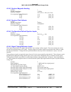
4.2.3.6 Configuration Defined DC Inputs
Quantity 2
Input Impedance, each leg > 83 KΩ
Reverse Fault Current
< 200 µA
Input Voltage Range
±5 VDC
Input Filter
0.1 Second Low Pass, ± 10%
Input Type Differential
Broken Wire Detect Input will be biased less than -6 VDC
Pin Assignment (Signal Mnemonic):
#1 Signal (+)
#1 Return (-)
#2 Signal (+)
#2 Return (-)
J1-26
J1-27
J1-66
J1-47
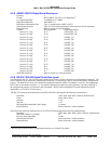
4.2.4 AC Analog Inputs
Unless otherwise specified
Input Impedance: X leg > 140 K
Ω
Input Impedance: Y leg > 140 KΩ
Input Impedance: Z leg > 140 KΩ
Maximum Reverse Fault Current
< 200 µA
Input Voltage Range ±11.8 VAC
RMS
± 20% (leg to leg)
Accuracy 2.5% linearity + 0.1% full scale offset
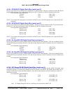
4.2.4.1 Synchro Roll Attitude
Quantity 1
Synchro Angle Range ±80 deg
Reference Voltages Not Required
Pin Assignment (Signal Mnemonic):
X leg
Y leg
Z leg
J1-1
J1-21
J1-2
(SYN_1X)
(SYN_1Y)
(SYN_1Z)


