


Honeywell
MK VI MK VIII EGPWS Installation Design Guide
Proprietary notice on title page applies
CAGE CODE: 97896 SCALE: NONE SIZE: A DWG NO: 060-4314-150 REV:
SHEET
91
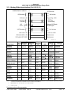
3.10 Category 8 – Radio Altitude Input Select
Category 8 defines the Radio Altitude and Decision Height interface.
3.10.1 Radio Altitu de Input
Appendix E Table 5.3.8 defines the Radio Altitude Types and identifies the first MK VI/MK VIII EGPWS version
in which the option was available (see Effectivity entry).
Appendix E Tables 5.3.8-x, where x is the Radio Altitude Type number, define the format and electrical
interfaces required to support each Radio Altitude Type.
3.10.2 Decision H eight Discrete Input
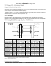
The Decision Height discrete (J1-33, Category 8) indicates to the MK VI/MK VIII EGPWC whether the aircraft is
above or below the selected Decision Height.
This discrete is typically connected to the Decision Height output on the Radio Altimeter indicator. If the
‘Minimums-Minimums’ callout is not wanted the Decision Height discrete should be left open.
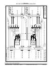
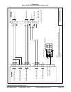
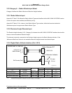
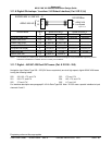
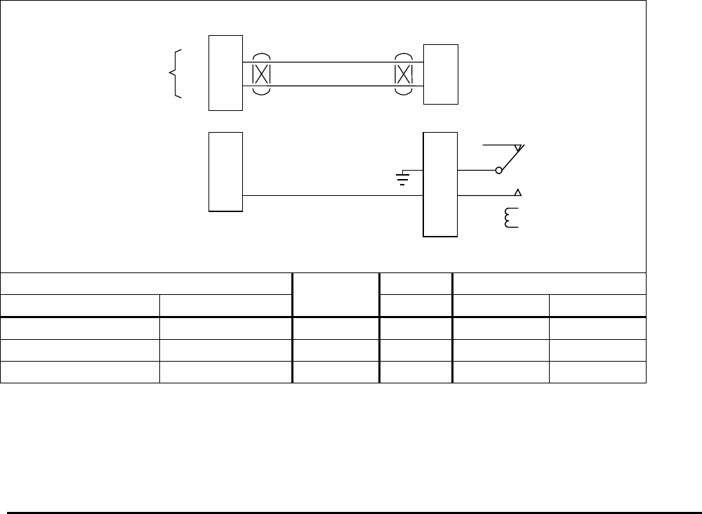
3.10.3 Digital Rad io Altitude Interface (Cat. 8 ID 2)
21
4
J2
Radio Altimeter R/T
A
B
EGPWS MK VI / MK VIII
A
B
ARINC 429
Radio Altitude
ARINC 429
DH Discrete (Gnd)
33
Radio Altimeter Indicator
DH out
J1
Digital-RA.vsd
DH wiper
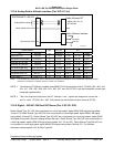
Vendor Model Ind. DH R/T
R/T Indicator SCALE wiper/out A B
Collins RAC-870 ALI-55 ARINC 429 P1-R/V P1-2 P1-3
Honeywell ALA-52A/B ARINC 429 MP-B2 MP-B3
Honeywell KRA-405B KNI-415/416 ARINC 429 P1-M/A P4051-B P4051-C
NOTE: The connector pin numbers given in the Table above are to the best knowledge of Honeywell EGPWS engineering. Please
contact the manufacturer’s customer service to confirm your installation.