


Honeywell
MK VI MK VIII EGPWS Installation Design Guide
Proprietary notice on title page applies
CAGE CODE: 97896 SCALE: NONE SIZE: A DWG NO: 060-4314-150 REV:
SHEET
132
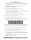
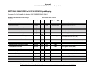
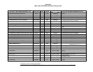
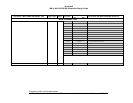
Signal Name –MK-VI GPWS (965-0686-001, -020) Signal Type Same Conn/Pin
Signal Type
< IN Out >
Signal Name -MK-VI/MK VIII EGPWS (Enhanced)
Audio Volume Control #1 Program Pin Progpin J1-26 < Analog (+) Spare
500’ Altitude Callout Program Pin Progpin J1-27 < Analog (-) Spare
Spare Discrete (+28VDC) Discrete J1-28 < 28vDisc Magnetic Heading Validity Discrete (+28VDC)
Radio Altimeter Validity (+28VDC) 28vDisc
X
J1-29 < 28vDisc Radio Altitude Validity Discrete (+28VDC)
Glideslope Deviation Low Level Validity (H) DC-AnalogL
X
J1-30 < Analog (+)
Glideslope Deviation Low Level Validity (+) and
Localizer Deviation Low Level (+Right)
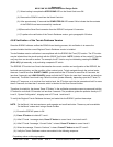
Spare #1 Discrete Discrete J1-31 < GDisc Display Selected Discrete #2 (GND)
Airspeed Expansion Discrete Discrete J1-32 < GDisc Display Selected Discrete #1 (GND)
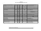
Decision Height DH Discrete (GND) Discrete
X
J1-33 < Gdisc DH Discrete (GND)
GPWS Self Test Discrete (GND) Discrete
X
J1-34 < GDisc
Self Test Discrete (GND) (from GPWS push to test
Sw)
Landing Gear Discrete (+28VDC) Discrete
X
J1-35 < 28vdisc Landing Gear Discrete (+28VDC)
External GPWS Audio Suppress Discrete (+28VDC) Discrete
X
J1-36 < 28vdisc Audio Inhibit Discrete (+28VDC)
Landing Flap Discrete (+28VDC) Discrete
X
J1-37 < 28vdisc Landing Flaps Discrete (+28VDC)
ILS Backcourse Approach Selectd Discrete (+28V) Discrete
X
J1-38 < 28vdisc Glideslope Inhibit Discrete (+28VDC)
ILS Frequency Selected Discrete (+28VDC) Discrete
X
J1-39 < 28vdisc ILS 1 Tuned Discrete (+28VDC)
Power Input (+28VDC) PWR/GND
X
J1-40 < PWRH Power Input 28VDC (+)
Power Input (GND) PWR/GND
X
J1-41 < PWRL Power Input 28VDC (return)
Chassis Ground GND
X
J1-42 < GND__C Chassis Ground
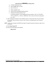
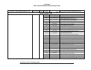
Barometric Altitude Rate Input (-) DC-AnalogL J1-43 < Analog (-) Barometric Altitude (-)
Airspeed Input (-) DC-AnalogL J1-44 < Analog (-) Air Temperature (-)
Radio Altimeter Input (-) DC-AnalogL
X
J1-45 < Analog (-)
Radio Altitude: ARINC 552 or ALT-55 (-)
RT-200/300 Precision (+)
Glideslope Deviation Input (+ down) DC Analog
X
J1-46 < Analog (-) Glideslope Deviation Low Level (+down)
Test Point #1 Test point J1-47 < Analog (-) Spare
Test Point #2 Test point J1-48 < 28vdisc Localizer Validity Discrete (+28VDC)
Test Point #3 Test point J1-49 Lampout > (gnd)
Terrain Select Relay Output #2 (to TERR lamp and/or
Relay)
Test Point #4 Test point J1-50 Monitor Out > (gnd) Windshear Inop Lamp Output (monitor)
Test Point #5 Test point J1-51 Lampout > (gnd) Terrain Pop Up Discrete Output
Test Point #6 Test point J1-52 Lampout > (gnd)
Steep Approach
Windshear Caution
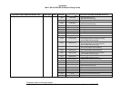
Test Point #7 Test point J1-53 < GND Temperature Probe (GND)
Test Point #8 Test point J1-54 Lampout > (gnd)
Terrain Select Relay Output #1 (to TERR lamp and/or
Relay)